EXTRACTING THE COOLING MODULES
The cooling modules can be pulled out for service and
transport.
NOTE
The heat pump must not be moved when only
the lower cooling module has been pulled out.
If the heat pump is not secured in position the
upper cooling module must always be removed
before the lower one can be pulled out.
Caution
The cooling modules are easier to remove if
drained first (see page 44).
Weight of the cooling module
Weight (kg)Type (F1345)
13024 kW
13530 kW
143.540 kW
14460 kW
NOTE
Switch off F1345 and turn off the current at
the safety breaker.
Caution
Remove the front cover according to the de-
scription in the installer manual.
1.
Close the shut-off valves outside the heat pump.
Drain the cooling module(s) according to the instruc-
tions on page 44.
2.
Remove the side panel to be able to remove the
display unit (this procedure need only be done if you
are going to pull out the upper cooling module).
3.
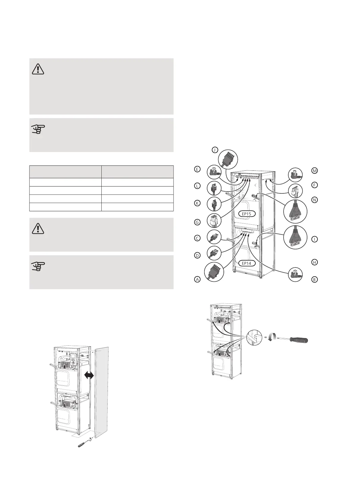
Disconnect the connectors for the relevant cooling
module.
Cooling module EP15 (upper)
• XF8 (L)
• XF9 (M)
• EP15-AA100:XF1 (N)
• XF2 (J)
• XF6 (E)
• XF7 (K)
Cooling module EP14 (lower)
• XF10 (F)
• XF11 (G)
• XF13 (H)
• EP14-AA100:XF1 (I)
• XF1 (A)
• XF3 (B)
• XF4 (C)
• XF5 (D)
4.
Remove the screws (two for each cooling module).
47Chapter 4 | ServiceNIBE F1345