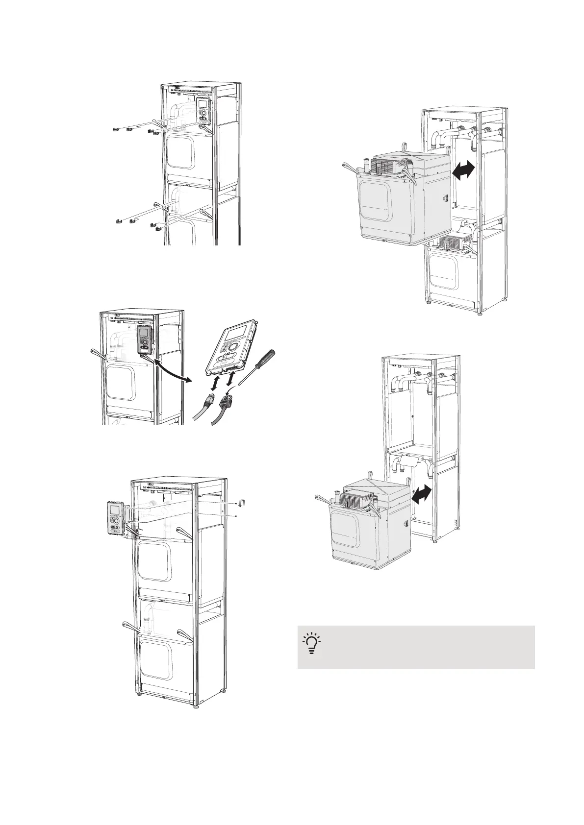
5.
Pull off the clips (four for each cooling module) and
separate the pipes carefully.
6.
Remove the connector from the underside of the
display unit (this procedure need only be done if you
are going to pull out the upper cooling module).
7.
Remove the two screws holding the display unit in
the frame (this procedure only needs to be done if
you are going to pull out the upper cooling module).
8.
Carefully pull out the upper cooling module (EP15)
using the module's lifting eyelets.
Use a height adjustable relief surface for this proced-
ure.
9.
Carefully pull out the lower cooling module (EP14)
using the module's lifting eyelets.
If the heat pump is not secured in position the upper
cooling module must always be removed before the
lower one can be pulled out.
TIP
The cooling module is installed in reverse order.
NIBE F1345Chapter 4 | Service48