CONNECTING EXTERNAL OPERATING
VOLTAGE FOR THE CONTROL SYSTEM
NOTE
Mark up any junction boxes with warnings for
external voltage.
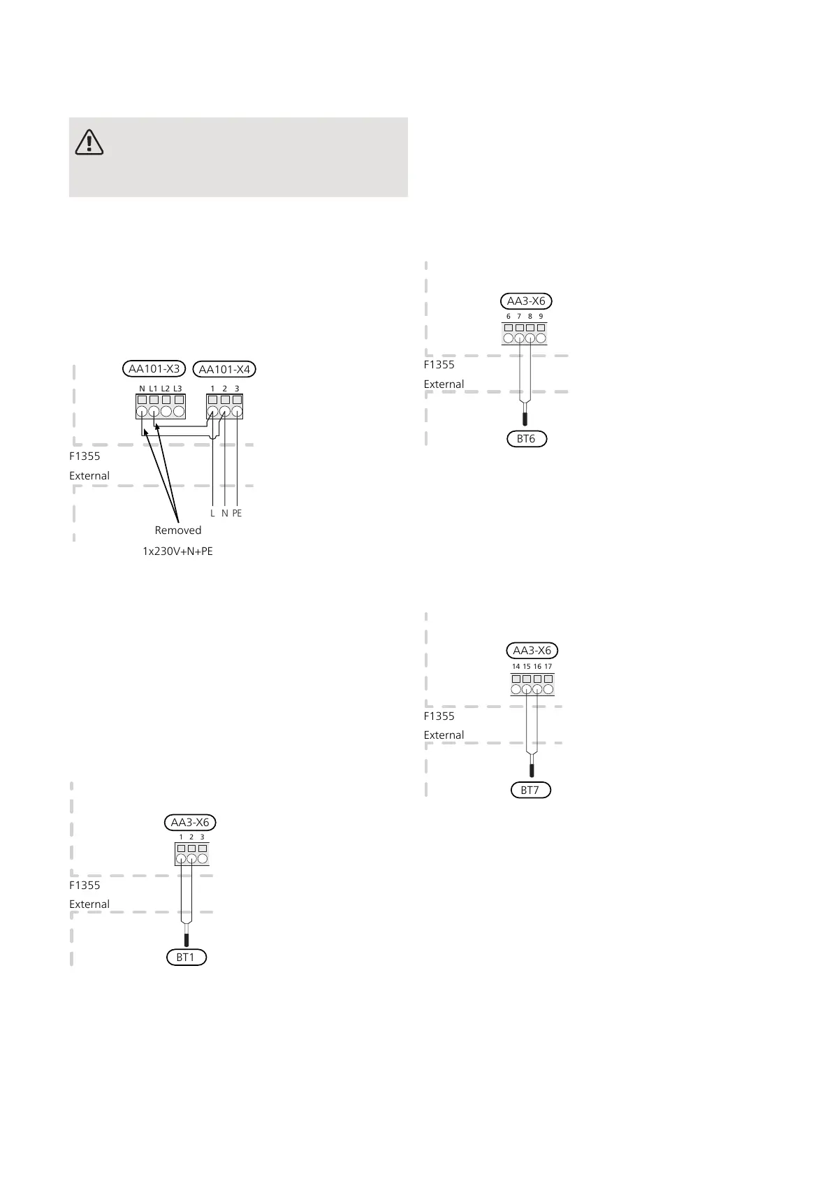
When connecting external operating voltage with separ-
ate earth-fault breaker, remove the cables between
terminal block AA101-X3:N and AA101-X4:2 and
between terminal block AA101-X3:L1 and AA101-X4:1
(as illustrated).
Operating voltage (1x230V+N+PE) is connected to
AA101-X4:3 (PE), AA101-X4:2 (N) and AA101-X4:1 (L)
(as illustrated).
F1345
E
xternt
L1N L2 L3
1 2 3
PENL
External
F1355
AA101-X3
1x230V+N+PE
AA101-X4
Removed
OUTSIDE SENSOR
Install the outside temperature sensor (BT1) in the shade
on a wall facing north or north-west, so it is unaffected
by the
morning sun.
Connect the sensor to terminal block AA3-X6:1 and AA3-
X6:2. Use a twin core cable with a cable area of at least
0.5 mm².
If a conduit is used it must be sealed to prevent condens-
ation in the sensor capsule.
TEMPERATURE SENSOR, HOT WATER
CHARGING
The temperature sensor, hot water charging (BT6) is
placed in the submerged tube on the water heater.
Connect the sensor to terminal block AA3-X6:7 and AA3-
X6:8. Use a twin core cable with a cable area of at least
0.5 mm².
Hot water charging is activated in menu 5.2 or in the
start guide.
TEMPERATURE SENSOR, HOT WATER TOP
A temperature sensor for hot water top (BT7) can be
connected to F1355 for showing the water temperature
at the top of the tank (if possible).
Connect the sensor to terminal block AA3-X6:15 and
AA3-X6:16. Use a twin core cable with a cable area of
at least 0.5 mm².
23Chapter 5 | Electrical connectionsNIBE F1355
 Loading...


