TEMPERATURE SENSOR, EXTERNAL FLOW
LINE
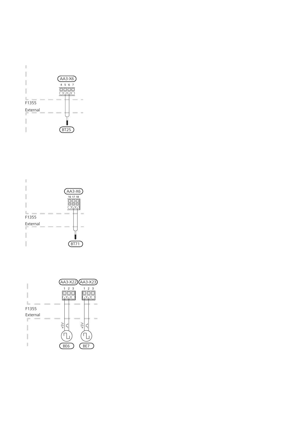
Connect temperature sensor, external supply line (BT25)
to terminal block AA3-X6:5 and AA3-X6:6. Use a twin
core cable with a cable area of at least 0.5 mm².
TEMPERATURE SENSOR, EXTERNAL
RETURN LINE
Connect temperature sensor, external return line (BT71)
to terminal block AA3-X6:17 and AA3-X6:18. Use a twin
core cable with a cable area of at least 0.5 mm².
CONNECTING EXTERNAL ENERGY METER
One or two energy meters (BE6, BE7) are connected to
terminal block X22 and/or X23 on input board (AA3).
F1345
E
xternt
1 2 3 1 2 3
+5V
+5V
External
F1355
AA3-X22
BE6
AA3-X23
BE7
Activate the energy meter(s) in menu 5.2.4 and then set
the desired value (energy per pulse) in menu 5.3.21.
NIBE F1355Chapter 5 | Electrical connections24
 Loading...


