ROOM SENSOR
F1355 can be supplemented with a room sensor (BT50).
The room temperature sensor has up to three functions:
1.
Show current room temperature in the heat pump's
display.
2.
Option of changing the room temperature in °C.
3.
Makes it possible to change/stabilise the room
temperature.
Install the sensor in a neutral position where the set
temperature is required. A suitable location is on a free
inner wall in a hall approx. 1.5 m above the floor. It is
important that the sensor is not obstructed from meas-
uring the correct room temperature by being located,
for example, in a recess, between shelves, behind a
curtain, above or close to a heat source, in a draft from
an external door or in direct sunlight. Closed radiator
thermostats can also cause problems.
F1355 operates without the sensor, but if you want to
read the home’s indoor temperature from the display,
the sensor must be installed. Connect the room sensor
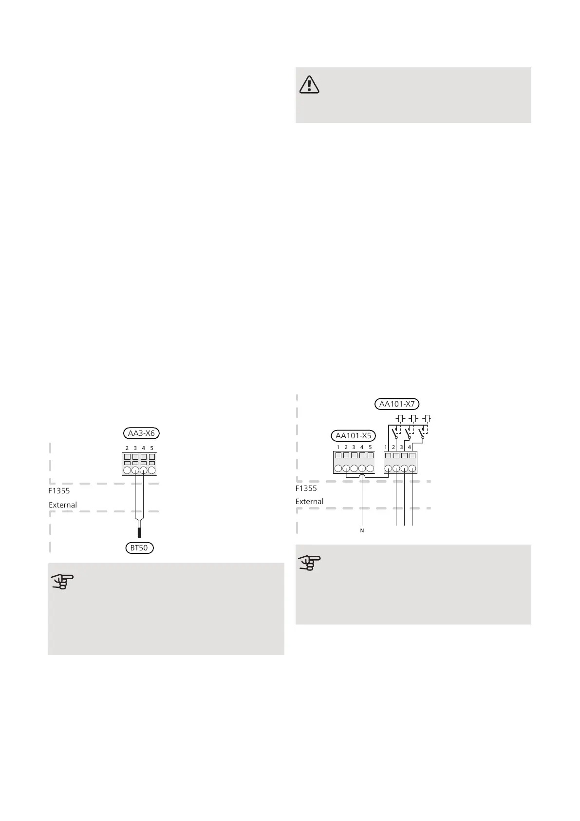
to AA3-X6:3 and AA3-X6:4.
If the sensor is to be used to change the room temper-
ature in °C and/or to change/stabilise the room temper-
ature, the sensor must be activated in menu 1.9.4.
If the room sensor is used in a room with under floor
heating it should only have an indicatory function, not
control of the room temperature.
Caution
Changes of temperature in the accommodation
take time. For example, short periods of
change combined with under floor heating will
not result in a noticeable difference in the room
temperature.
STEP CONTROLLED ADDITIONAL HEAT
NOTE
Mark up any junction boxes with warnings for
external voltage.
External step-controlled additional heat can be controlled
by up to three potential-free relays in F1355 (3 step linear
or 7 step binary). With the AXC 50 accessory, a further
three potential-free relays are used for additional heat
control, which then gives max 3+3 linear or 7+7 binary
steps.
Step in occurs with at least 1 minute interval and step
outs with at least 3 seconds interval.
Connect the common phase to terminal block AA101-
X7:1.
Step 1 is connected to terminal block AA101-X7:2.
Step 2 is connected to terminal block AA101-X7:3.
Step 3 is connected to terminal block AA101-X7:4.
The settings for step controlled additional heat are made
in menu 4.9.3 and menu 5.1.12.
All additional heat can be blocked by connecting a poten-
tial-free switch function to AUX input on terminal block
AA3-X6 and AA101-X10. The function must be activated
in menu 5.4.
F1345
E
xternt
1 2 3 4
1 2 3 4
N
5
External
F1355
AA101-X5
AA101-X7
Caution
If the additional heat’s operating voltage is
230 V~, voltage can be taken from AA101-
X5:1 - 3. Connect the neutral from the external
additional heat to AA101-X5:4 - 6.
27Chapter 5 | Electrical connectionsNIBE F1355
 Loading...


