T PT
-AA5
-EP30
-BT53
-EP8
-GP4
-QM45
-QM43
-QM44
-CM5
-FL4
-FL2
-CM1
-GP14
-RM6
-RM4
-GP30
10 NIBE VVM 500
Electrical connections
General
All electrical equipment, except the outdoor sensors, room sen-
sors and the current sensors are already connected at the factory.
• Disconnect the indoor module before insulation testing the
house wiring.
• When the building is equipped with an earth-fault breaker,
VVM 500 should be equipped with a separate one.
• The electrical circuit diagram for the indoor module is at the
end of this Installer manual.
• Communication and sensor cables to external connections
must not be laid close to high current cables.
• The minimum area of communication and sensor cables to
external connections must be 0.5 mm
2
up to 50 m, for ex-
ample EKKX or LiYY or equivalent.
• You must use cable grommets UB1 and UB2 when cable
routing in VVM 500. In UB1 and UB2 the cables are inserted
through the indoor module from the back to the front.
Miniature circuit-breaker
The indoor module and a large proportion of its internal com-
ponents are internally fused by a miniature circuit breaker (FA1).
Temperature limiter
The temperature limiter (FD1) cuts the current supply to the elec-
trical addition if the temperature rises to between 90 and 100 de-
grees C and is manually reset.
Settings
Electrical addition - maximum output
The immersion heater can be set to a maximum of 9 kW. Deliv-
ery setting is 9 kW.
The immersion heater output is divided into 4 steps, according to
the table in the Installer manual.
Setting maximum output in the electrical addition is done in
menu 5.1.12.
Standby mode
When the indoor module switch (SF1) is set to emergency mode
only the most necessary functions are activated.
The hot water capacity is reduced.
The load monitor is not connected.
Temperature is fixed in the flow line
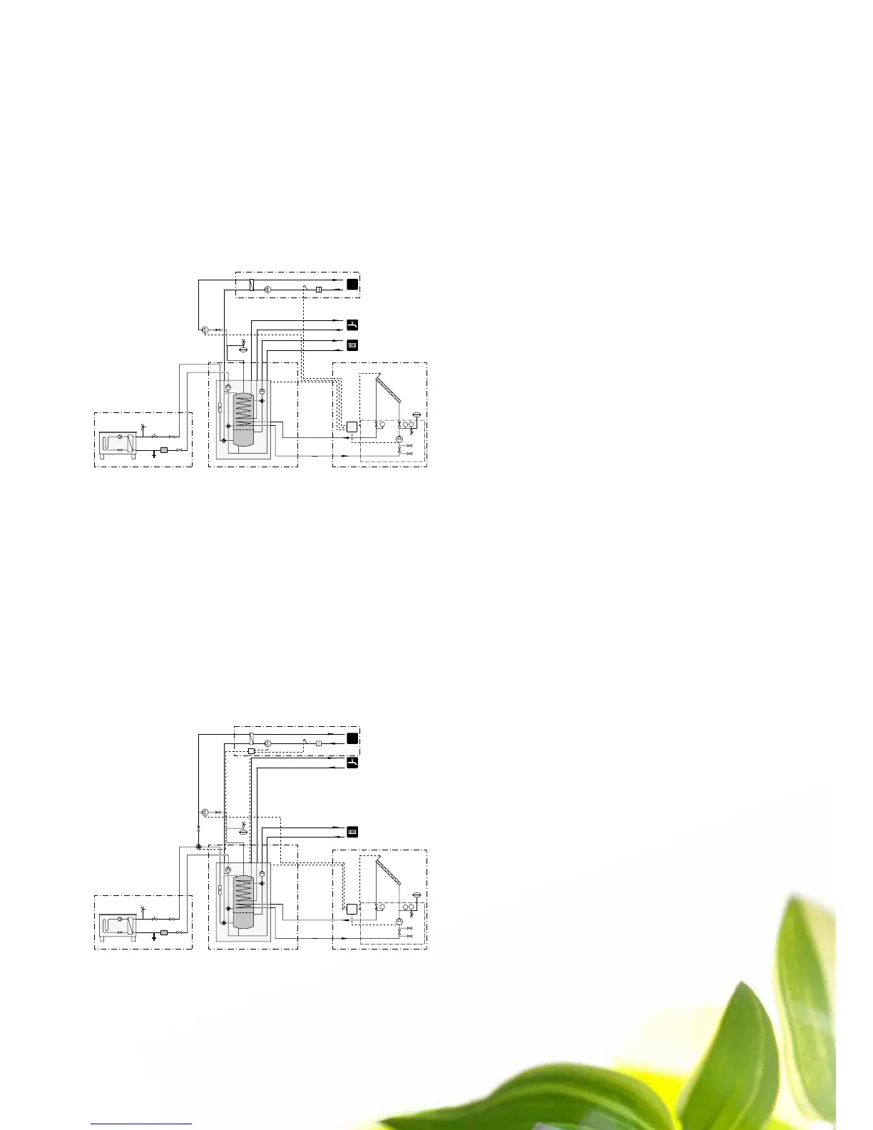
Pool and solar
In this example the solar installation is connected. When solar heat-
ing has heated the tank to the desired stop temperature, the solar
heat will be transferred to the pool. Charging the pool continues un-
til the pool is fully heated or until the temperature in the tank falls
below the desired stop temperature.
Pool with heat pump and solar
Charging of the pool is controlled by the pool sensor. In the case
of low pool temperatures, the shuttle valve reverses direction and
opens towards the pool exchanger. This connection requires the
POOL 500 accessory, see Accessories on the rear cover and the in-
stallation manual for POOL 500.
In this example the solar installation is connected. When solar heat-
ing has heated the tank to the desired stop temperature, the solar
heat will be transferred to the pool. Charging the pool continues un-
til the pool is fully heated or until the temperature in the tank falls
below the desired stop temperature.
INSTALLATION

 Loading...


