500
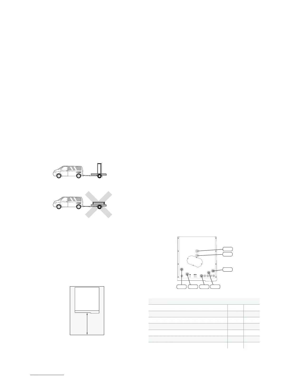
XL4
XL2
CM1
XL8
XL9
XL3
XL1
4 NIBE VVM 500
Transport and storage
NIIBE VVM 500 must be transported and stored upright and dry.
The VVM 500 may, however, be carefully laid on its back when
being moved into a building.
Quick and simple installation
• No extra buffer tank for the heating system is required as
VVM 500 fully controls the heat pump and the heating sys-
tem.
• New control with colour display and USB port.
• Installation help with step by step guide through the start-
up process.
• Automatic setting of flow across heat pump and heating sys-
tem.
• Factory installed components for best operational reliability
and safe installation.
• Complete accessory program.
Maintenance
A minimum level of maintenance is required. Only safety valves
require checking. All essential components can be accessed from
the front. This facilitates service and maintenance.
Installation
VVM 500 is easy to install. All pipe connections are easily accessi-
ble. This is especially useful for the replacement market.
Equipment
VVM 500 is equipped with a drain and reversing valve. In addi-
tion, VVM 500 is equipped with climate controlled automatic by-
passes with outdoor and flow sensors, shunt valve, charge and
circulation pump.
Expansion vessel
Dimensioned as 5 % of the maximum system volume (that is 500
litres plus maximum circulating volume in the hot circuit).
Design
VVM 500 is equipped with an intelligent control. This makes for
easy operation at the same time as always enabling the indoor
module to run as efficiently as possible. The control manages the
automatic bypass and circulation pumps. Current temperatures
and set values can be shown on the display.
The insulation consists of moulded, freon-free polyurethane
which is equivalent to approximately 200 mm mineral wool.
The outer casing is of white powder-coated steel plate.
Pipe dimensions
Assembly
Position VVM 500 on a firm base that can bear its weight, prefer-
ably on a concrete floor or foundation. Use the product's adjust-
able feet to obtain a horizontal and stable set-up.
The area where VVM 500 is located must be equipped with floor
drainage.
Installation area
Leave a space of 500 mm in front of the product. All service on
VVM 500 can be carried out from the front.
NOTE! Leave 10-25 mm free space between the indoor module
and the wall behind for routing of cables and pipes.
Connection
CM1 Expansion tank (connection) Ø G20 internal
XL1 Heating medium, flow line Ø G25 internal
XL2 Heating medium, flow line Ø G25 internal
XL3 Cold Water リ G25 internal
XL4 Hot Water Ø G25 exernal
XL8 Connection, docking in heating medium Ø G25 internal
XL9 Connection, docking out heating medium Ø G25 internal
GOOD TO kNOW ABOUT NIBE
™
VVM 500

 Loading...


