12 NIBE VVM 500
B
A
C
D
E
F
VVM 500
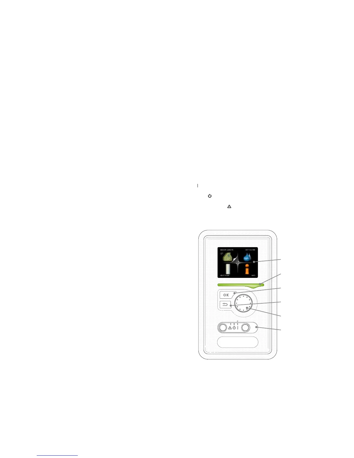
THE DISPLAy
Display unit
Display, A
Instructions, settings and operational information are shown on
the display. The easy-to-read display and menu system facilitates
navigation between the different menus and options to set the
comfort or obtain the information you require.
Status lamp, B
The status lamp indicates the status of the heat pump. It:
• lights green during normal operation.
• lights yellow in emergency mode.
• lights red in the event of a deployed alarm.
OK button, C
The OK button is used to:
• confirm selections of sub menus/options/set values/page in
the start guide.
Back button, D
The back button is used to:
• go back to the previous menu.
• change a setting that has not been confirmed.
Status lamp
Display
OK button
Back button
Control knob
Switch
Control knob, E
The control knob can be turned to the right or left. You can:
• scroll in menus and between options.
• increase and decrease the values.
• change page in multiple page instructions (for example help
text and service info).
Switch, F
The switch assumes three positions:
• On (
)
• Standby (
)
• Emergency mode (
)
A large, easy to read multicoulour display gives everyone the chance to
maximize the energy saving potential of this exciting green technology!

 Loading...


