25
POWER
OFF
120
AUTO CLOSE
TIME
MIN MAX
STALL
FORCE
ON OFF
SG1
ED1
K1
06
AVR-ISP
D1
C2
C7
C15
LED3
D15
R20
IC4
D16
D13
D14
K2
BATT- BATT+
STATUS
ANT SHLD
S9.8874
EDGE
COM
LOCK+
LOCK -
M_BLK
M_RED
VAR2
GRN
VAR3
VAR3
VAR1
VAR4
VAR5
PF1
VAR6
WHT
CYCLE
EXIT
SAFETY
COM
CHGR
CHGR
4
7
5
6
8
1
2
3
9
10
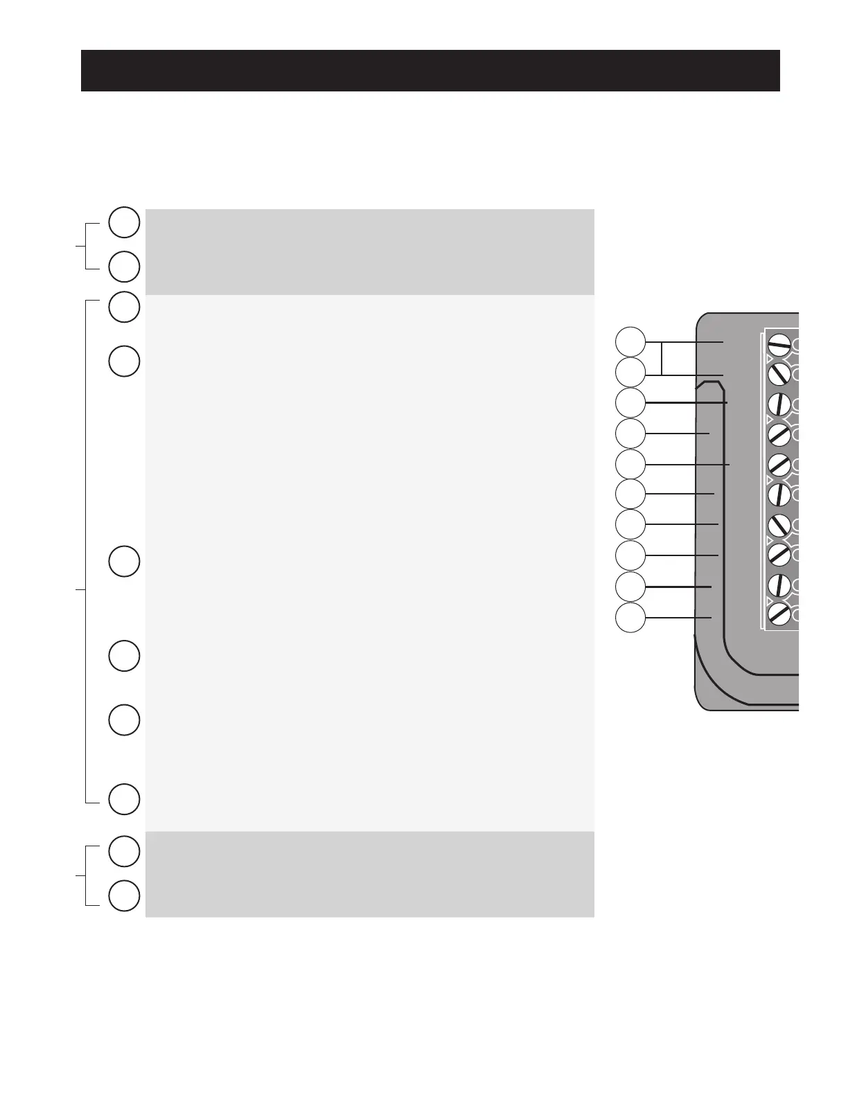
NOTES:
• All accessory inputs are dry-contact, normally open, inputs. DO NOT apply external voltage sources to these inputs.
• All accessory inputs are connected with respect to COMMON terminal.
LOCK OUTPUTS
CHARGE POWER
INPUTS
ACCESSORY INPUTS
Control Board Connections
1
CHGR: Power Input Terminals:
• Input terminals for transformer.
2
CHGR: Power Input Terminals:
• Input terminals for transformer or solar panel.
3
COM:
• Common/Negative terminal for accessory devices and negative
wire from solar panel(s).
4
SAFETY: (Typically for use with photo beam device, loop detector or
other non-contact sensors)
• Activation of this input while the gate is closing, or at a position
other than fully open or fully closed will cause the gate to stop
and return to the opened position.
• Activation of this input while the gate is opening has no effect.
(gate will continue to open)
• Activation of this input while the gate is open will prevent gate
from closing.
• Activation of this input while at open limit will restart the auto
close time (if enabled).
5
EXIT: (Typically for use with exit loop or wand)
• Activation of this input will open the gate if it’s not already at the
open position.
• Activation of this input while at open limit will restart the auto
close time (if enabled).
6
CYCLE: (Typically for use with doorbell button or hard wired keypad)
• Each activation at this input will cycle the operation as follows:
….→ OPEN → STOP → CLOSE → STOP → OPEN → …
7
EDGE: (Typically for use with contact edge sensor)
• Activation of this input while gate is moving will cause it to
reverse direction for 2 seconds.
• Activation of this input while idle will prevent gate from running.
8
COM:
• Common/Negative terminal for accessory devices.
9
LOCK +: Positive terminal to connect electro-mechanical lock. (FM143)
10
LOCK - : Negative terminal to connect electro-mechanical lock. (FM143)