6
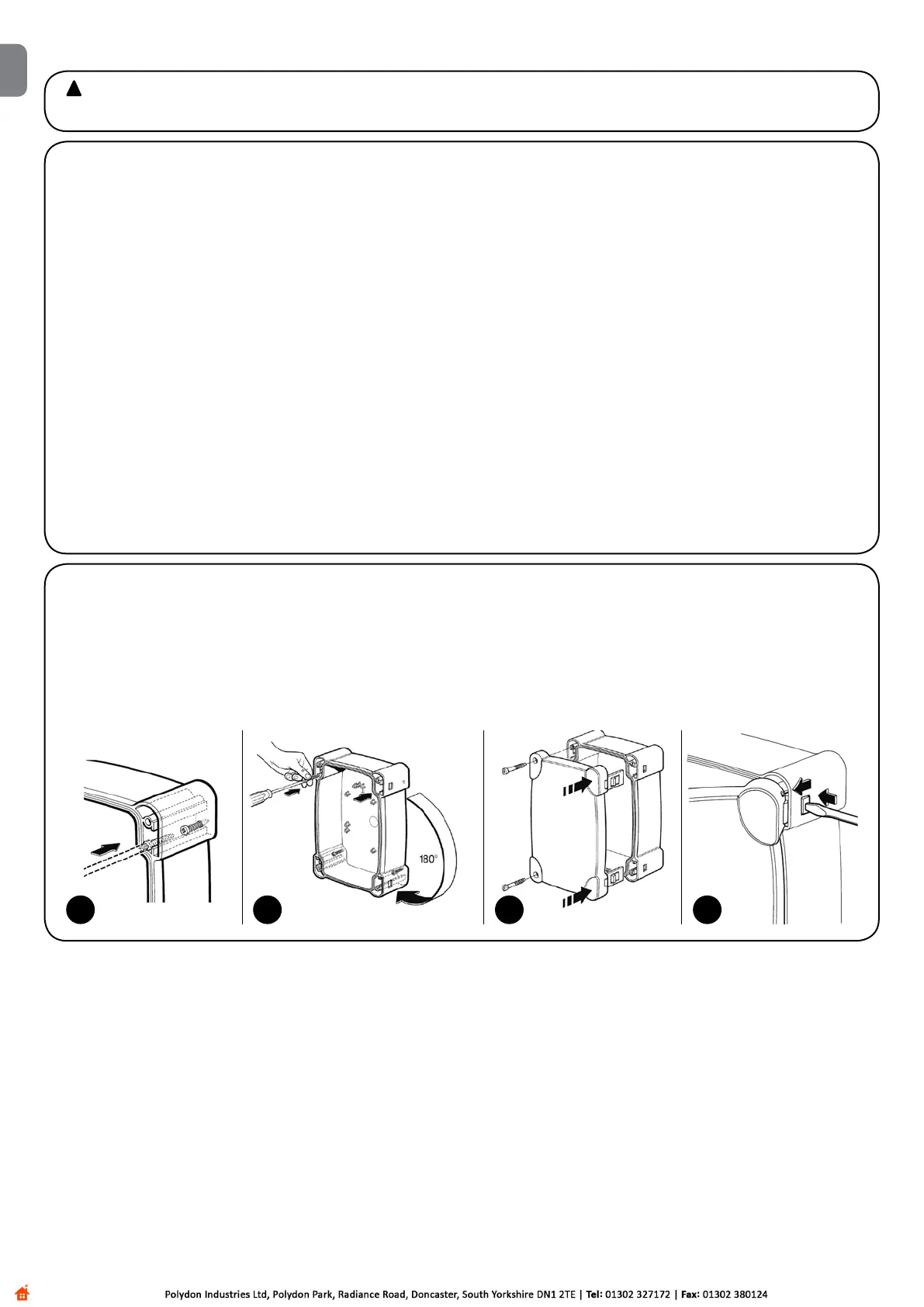
3.2) Fixing the control unit
Insertthetwoscrewsintheupperholesprovided,slidingthemontheguideasing.3aandpartlyscrewingthemin.Turnthecontrolunit
through 180° and perform the same operation with the other 2 screws. Fix the control unit on to the wall.
Fixthecoveronthedesiderdpart(withopeningontherightorleft),pressrmlyonthearrows.
To remove the cover, press with a screwdriver on the join and push upwards at the same time.
!
and the directions provided in this manual.
3) Installation
3.1) Preliminary checks
Before proceeding with the installation:
•Checkthatallthematerialsareinexcellentcondition,suitablefor
use and compliant with current standards.
•Ensurethatthestructureofthegateissuitableforautomation.
•Ensurethatthemountingpositionsofthevariousdevicesarepro-
tectedfromimpactandthatthemountingsurfacesaresufciently
sturdy.
•Installcable or pipe leads only atthebottom of the unit; for no
reason whatsoever must the side and top walls be perforated. The
cables must only enter the unit from the bottom!
•Insertsuitablemechanicalstops,anchoredtotheground,bothfor
opening and closing manoeuvres.
•Componentsmustneverbeimmersedinwaterorotherliquids.
Keep away from heat sources and open ames; in acid, saline
or potentially explosive atmosphere; this could damage A60 and
cause malfunctions or hazardous situations.
•Ifthereisanaccessdoorintheleaf,orwithintherangeofmove-
ment of the gate, make sure that it does not obstruct normal travel.
Mount a suitable interlock system if necessary.
•Onlyconnectthecontrolunittoapowersupplylineequippedwith
a safety grounding system.
•Thepowersupplylinemustbeprotectedbysuitablemagnetother-
mal and differential switches.
• A disconnection device must be inserted in the power supply
linefromtheelectricalmains(thedistancebetweenthecontacts
must be at least 3.5mm with an overvoltage category of III) or
equivalent system, for example an outlet and relative plug. If the
disconnection device for the power supply is not mounted near the
automation, it must have a locking system to prevent unintentional,
unauthorised connection.
3a 3b 3c 3d
EN