2.2.2) Description of connections
A brief description of the possible control unit output connections follows.
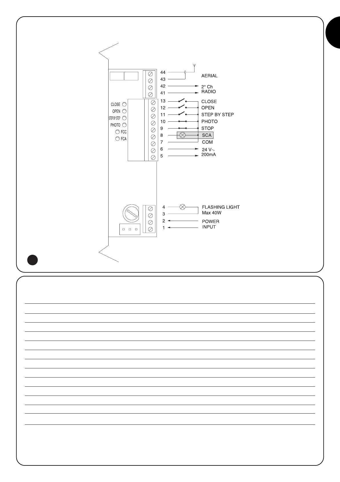
Terminals Functions Description
1-2 : Power input = Mains power line
3-4 : Flashing light = Output for connecting flashing light to mains voltage (max. 40W)
5-6 : 24 Vac = 24Vac output to 24Vac services (Photo, Radio, etc.) Max. 200mA
7 : Common = Common for all inputs
8:
Gate open indicator
= Max. 24 Vac output for gate open indicator 2W (Not used on OTTO)
9 : Stop = Input for stopping the manoeuvre with a brief reverse phase
10 : Photo = Input for safety devices (photocells, pneumatic edges)
11 : Step-by-step (PP) = Input for cyclic functioning (“Open” - “Stop” - “Close” - “Stop”)
12 : Open = Input for opening
13 : Close = Input for closing
41-42 : 2nd Radio Ch = Output for the second radio receiver channel if there is one
43-44 : Aerial = Input for the radio receiver aerial