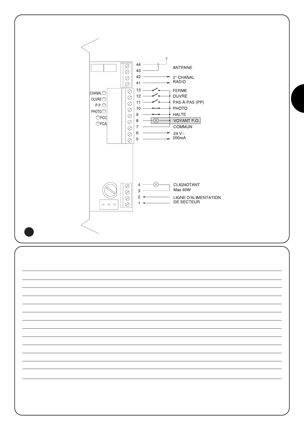
2.2.2) Description des connexions
Nous donnons ci-après une brève description des connexions possibles de l’armoire de commande vers l’extérieur.
Bornes Fonctions Description
1-2 : Alimentation = Ligne d’alimentation de secteur
3-4 : Clignotant = Sortie pour connexion du clignotant à tension de secteur ( Max. 40W)
5-6 : 24 Vca = Alimentation services 24 Vca (Photo, Radio, etc.) Max. 200 mA
7 : Commun = Commun à toutes les entrées
8 : Voyant P.O. = Voyant portail ouvert 24 Vca max. 2W ( Non présent sur version OTTO)
9 : Halte = Entrée avec fonction d’arr
êt de la manœuvre avec brève inversion du mouvement.
10 : Photo = Entrée pour dispositifs de sécurité (Photocellules, barres palpeuses)
11 : Pas-à-pas (PP) = Entrée pour mouvement cyclique (“Ouvre” - “Stop” - “Ferme” - “Stop”)
12 : Ouvre = Entrée pour mouvement en ouverture
13 : Ferme = Entrée pour mouvement en fermeture
41-42 : 2e Canal Radio = Sortie de l’éventuel deuxième canal du récepteur radio
43-44 : Antenne = Entrée pour antenne du récepteur radio