16 – ENGLISH
5.2 DEVICE LEARNING
After connecting the power supply, the control unit must learn the devices
connected to the “BlueBus” and “STOP” inputs, and also the rotation
direction of the motor set on the selector. Moreover, this procedure rec
-
ognises and memorises the input and output expansion board connected
to the control unit. Before this phase, LEDs “L1” and “L2” will ash to
indicate that recognition of the devices must be carried out.
m
The learning phase must be carried out even if no device
is connected to the control unit.
To do this:
1. simultaneously press and hold the
f
and
g
but-
tons
2. release the buttons when LEDs “L1” and “L2” start ashing quickly
(after roughly 3 seconds)
3. wait a few seconds until the control unit has completed the device
learning phase
4. once this phase terminates, the “Stop” LED must be lit and LEDs
“L1” and “L2” must switch off. In case of initial installation, LEDs
“L3” and “L4” will start ashing.
12V OSE
Bluebus
Aerial
32
The self-learning phase of the connected devices can be repeated at any
time also after the installation, for example whenever a device must be
added or removed.
m
If the motor’s rotation direction must be reversed, the de-
vice learning procedure must be performed again. (Refer
to the “Inverting the direction of motor rotation” para-
graph);
5.3 MANUAL PROGRAMMING OF THE DOOR
OPENING AND CLOSING POSITIONS
Once the devices have been learned, the door opening and closing posi-
tions must be programmed manually.
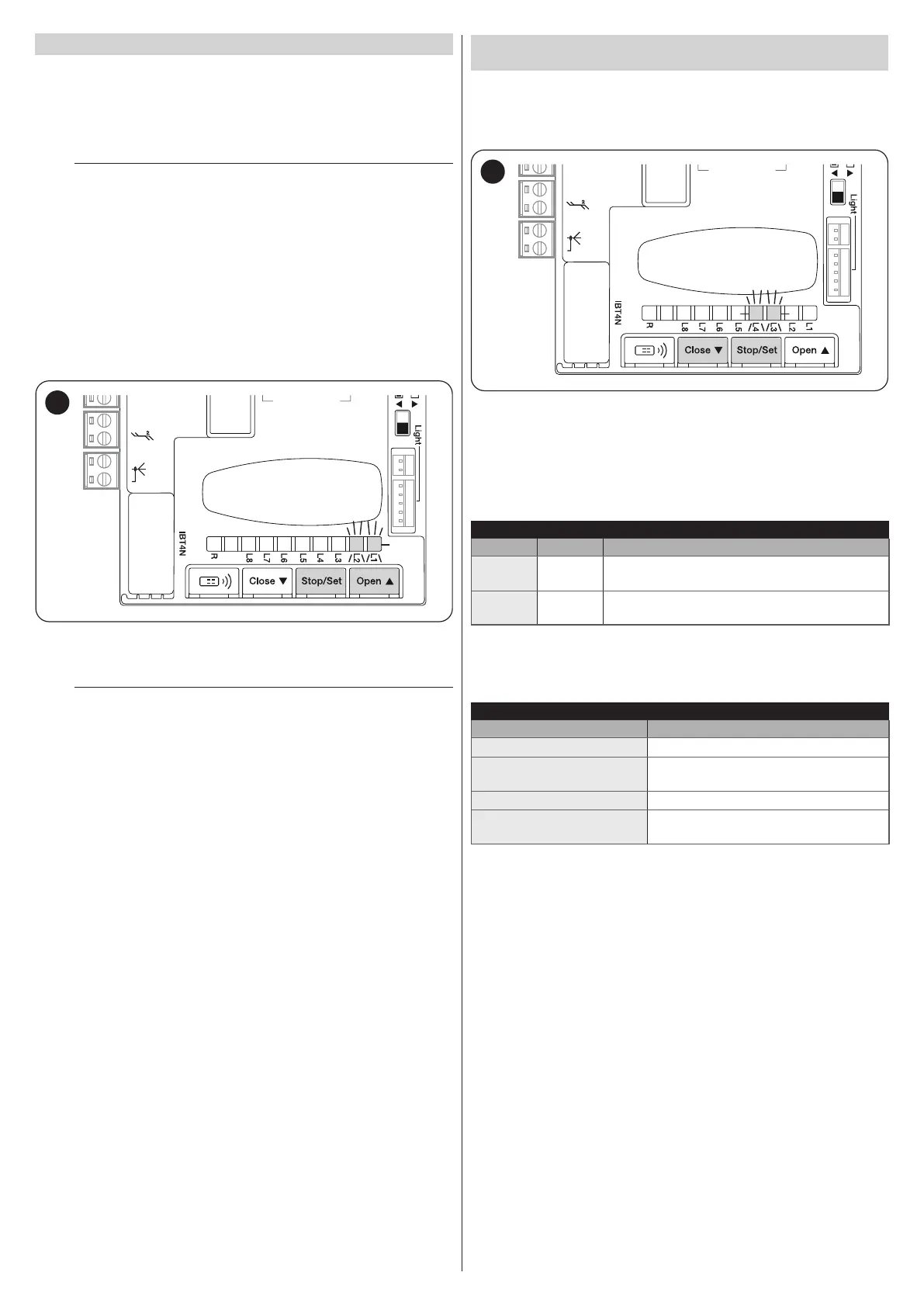
If these positions have not yet been memorised (or an invalid), LEDs “L3”
and “L4” will ash simultaneously (“Figure 33”).
12V OSE
Bluebus
Aerial
33
This procedure ensures rapid programming of the opening and closing po-
sitions, leaving the control unit to automatically calculate the intermediate
positions which can be modied later on through the “myNice Pro” app
and the compatible interfaces.
The positions involved in the programming are represented in “Table 7”
and shown in Figure “34”.
Table 7
PROGRAMMING POSITIONS
Position LED Description
A1 (max
opening)
L1
Maximum desired opening position. When the door
reaches this position it stops.
A0 (max
closing)
L8
Maximum closing position. When the door reaches
this position it stops.
The behaviour of the LEDs in the various programming phases is de
-
scribed in “Table 8”.
Table 8
DESCRIPTION OF THE POSITION PROGRAMMING LEDS
LED Description
L1 lit Opening position saved.
L1 ashing
Programming of the opening position in
progress.
L8 lit Closing position saved.
L8 ashing
Programming of the closing position in
progress.