10
7UDIƄFOLJKWLQERWKGLUHFWLRQV:
3GDETMBSHNMNESGDSQ@EjBKHFGSHMANSGCHQDBSHNMRHRL@HMKXSNBNMSQNKSGDkNVNESQ@EjBHMANSGCHQDBSHNMR@RSGDXFN@BQNRRSGDBNMSQNKKDC
QN@CA@QQHDQ CHEEDQDMSBNLL@MCHROK@BDCENQNODMHMFHMANSGCHQDBSHNMR//ENQDMSDQHMF@MC//.ODMENQKD@UHMFSVNSQ@EjBKHFGSR@QD
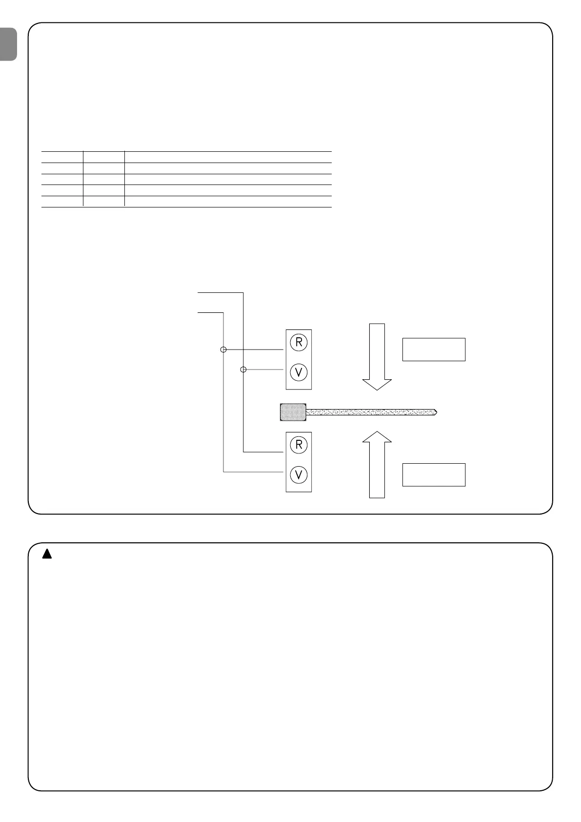
installed with the indications Red and Green, connected to the Bar Open Indicator and Courtesy Light outputs.
3GDSVNNTSOTSR@QDTRT@KKXNEE@MCRN@QDSGDSVNSQ@EjBKHFGSRVGDM@BNLL@MCHRFHUDMVHSG//SNDMSDQLNUDLDMSHRRS@QSDC@MCSGD
Bar Open Indicator output is activated: this means there will be a green light to enter and a red light to leave.
But should the command be given with the P.P.2, the Courtesy Light output will be activated and there will be a green light to leave and a red
KHFGSSNDMSDQ3GDKHFGSVHKKRS@XNMENQSGDDMSHQDNODMHMFL@MNDTUQD@MCENQSGDRTARDPTDMSO@TRDSHLDCTQHMFSGDBKNRHMFL@MNDTUQDANSG
SGDFQDDM@MCQDCKHFGSRVHKKAD@BSHU@SDCSGDQDRTKSADHMFXDKKNVSNHMCHB@SDSGDQDHRMNKNMFDQ@MXSQ@MRHSOQHNQHSXRDDS@AKD
The two Bar Open Indicator and Courtesy Light outputs can directly control small 24 V d.c. lamps for a total of 10 W. If stronger lamps have
SNADTRDCTRDSGDQDK@XROHKNSDCAXSGDTMHSNTSOTSRSG@SBNMSQNKHMSTQMSGDSQ@EjBKHFGSR
Red Green Meaning:
OFF OFF Bar closed, no passage in either direction
OFF ON Bar open, free transit
ON OFF Bar open, transit occupied
ON ON Bar closing and transit not controlled
TRAFFIC LIGHT
Lamp max 5W
COMMAND
CON : P. P.
COMMAND
CON : P. P. 2
ENTER
WIL
C.A. Indicator (9)
Cortesy light (8)
EXIT
This is the most important stage in the automation system instal-
lation procedure in order to ensure maximum safety levels. Testing
can also be adopted as a method of periodically checking that all the
various devices in the system are functioning correctly.
3DRSHMF NE SGD DMSHQD RXRSDL LTRS AD ODQENQLDC AX PT@KHjDC @MC
experienced personnel who must establish which tests to conduct
on the basis of the risks involved, and verify the compliance of the
system with applicable regulations, legislation and standards, in
O@QSHBTK@QVHSG@KKSGDOQNUHRHNMRNE$-RS@MC@QCVGHBGDRS@A-
lishes the test methods for automation systems for gates.
We recommend working in the manual mode with all the functions
CD@BSHU@SDCCHORVHSBGDR.%%HM@KKB@RDRVGDMXNT@QDVNQJHMF
in the manual mode and you release the control key the motor will
stop immediately.
$@BG BNLONMDMS NE SGD RXRSDL DF R@EDSX DCFDR OGNSNBDKKR
DLDQFDMBXRSNODSBQDPTHQDR@RODBHjBSDRSHMFOG@RDVDSGDQDENQD
recommend observing the procedures shown in the relative instruc-
tion manuals.
$MRTQDSG@SSGDHMRSQTBSHNMRNTSKHMDCHMSGHRL@MT@K@MCHMO@QSHBTK@Q
HMBG@OSDQf6 1-(-&2tG@UDADDMNARDQUDCHMETKK
ACheck that the bar is well balanced, adjusting the balancing
spring if necessary.
Release the boom gate using the special spanner and check that
the bar can move without any effort for the whole length of travel.
B/NVDQSGDTMHS@MCBGDBJSG@SUNKS@FDADSVDDMSDQLHM@KR@MC
1-3 is 230 / 120 Vac and 24 V a.c. between terminals 21-22.
RRNNM@RSGDTMHSHRONVDQDCSGDHMCHB@SNQKHFGSR+$#RNMSGD@BSHUD
HMOTSRRGNTKCKHFGSTOHM@CCHSHNMSGDf.*t+$#RGNTKCRS@QSk@RGHMF
almost immediately afterwards at regular intervals. If none of this hap-
pens, switch power off and check connections more carefully.
q 3GDS@RJNESGDf.*t+$#HMSGDBDMSQDNESGDB@QCHRSNRHFM@KSGD
RS@SDNESGDHMSDQM@KKNFHBQDFTK@Qk@RGHMF@SRDBNMCHMSDQU@KR
means the internal microprocessor is working and waiting for
commands. On the other hand, when the same microprocessor
QDBNFMHRDR@U@QH@SHNMHMSGDRS@SDNE@MHMOTSADHS@BNLL@MC
HMOTSNQETMBSHNMCHORVHSBG@CNTAKDPTHBJk@RGHMFHRFDMDQ@S-
DCDUDMHESGDDEEDBSRNESGDU@QH@SHNM@QDMNSHLLDCH@SD$WSQ@E@RS
k@RGHMFENQRDBNMCRLD@MRSG@SSGDTMHSG@RITRSADDMONVDQDC
6) Testing
EN