7
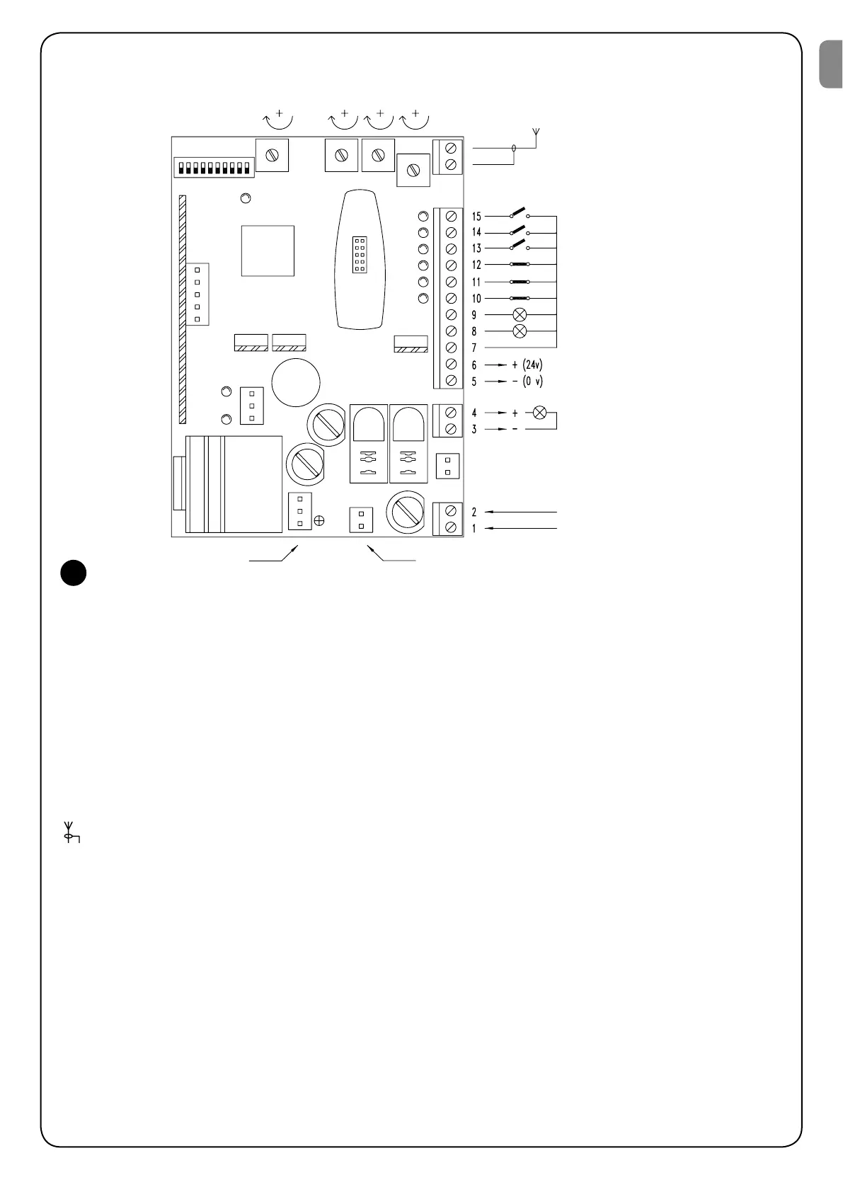
3.3) Description of the connections
Here is a brief description of the possible connections of the unit to the outside:
1-2 : 230 V a.c. = 230 V a.c. 50/60 Hz
3-4%K@RGHMFKHFGS.TSOTSENQBNMMDBSHNMSNSGD5CBk@RGHMFKHFGSL@WHLTLK@LOONVDQ6
5-65CB5CBNTSOTSENQRTOOKXHMF@BBDRRNQHDR/GNSNBDKK1@CHNDSBL@WHLTLL
7"NLLNM"NLLNMENQ@KKHMOTSRSDQLHM@KB@M@KRNADTRDC@RSGD"NLLNM
8 : Courtesy Light = 24 V d.c. output for the courtesy light, maximum output power 10 W
9" (MCHB@SNQ(MOTSVHSG23./ETMBSHNM$LDQFDMBXRGTSCNVMNQDWSQDLDR@EDSX
102SNO (MOTSENQR@EDSXCDUHBDR/GNSNBDKKROMDTL@SHBDCFDR
11/GNSNBDKK(MOTSENQR@EDSXCDUHBDRVHSGSQHFFDQHMFHMSGDNODMHMFOG@RD/GNSNBDKKROMDTL@SHBDCFDR
12 : Photocell2 = Input for safety devices with triggering
132SDOAX2SDO(MOTSENQBXBKHBETMBSHNMHMF./$-23./"+.2$23./
14.ODM3HLDQ(MOTSENQNODMHMFVGHBGB@MADSHLDQBNMSQNKKDC
15 : Close = Input for closing
: Aerial = Input for the radio receiver aerial
The remaining connections are done in the factory but for the sake of completeness here is the list:
TRANS.PRIM. = Primary of the power transformer
TRANS.SECOND. = Secondary of the power transformer
MOTOR = Output for 24 V d.c. motor connection
There are an additional two slots for optional cards:
RADIO = Slot for Nice radio receivers
CHARGE = Slot for battery charge card
Aerial
OK
FCA
FCC
CHARGE
RADIO
Close
Open-Timer
Step-by-Step
Photocell2
Photocell
Stop
C.A. Indicator
Courtesy Light
Common
24 Vdc
max 200 mA
Flashing light 24 Vdc
max 25 W
230 Vac
50-60 Hz
Primary of the power transformerSecondary of the power transformer
3
EN