5
2.1) Operating limits
"G@OSDQf3DBGMHB@K"G@Q@BSDQHRSHBRtOQNUHCDRSGDNMKXC@S@MDDCDCSNCDSDQLHMDVGDSGDQSGDOQNCTBSR@QDRTHS@AKDENQSGDHMSDMCDC@OOKH-
cation.
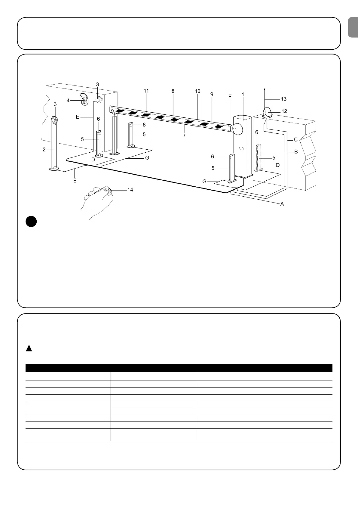
2.2) Typical system
NOTE: This diagram only shows a possible application of the unit and should be considered merely as an example. Only an in-depth analysis
NESGDQHRJRNESGDf,@BGHMDtF@SD@MC@OQNODQDU@KT@SHNMNESGDDMCTRDQQDPTHQDLDMSRVHKKAD@AKDSNDRS@AKHRGGNVL@MX@MCVGHBGDKD-
ments must be installed.
1. WIL Barrier
2. Selector post
3. *DXNODQ@SDCRDKDBSNQRVHSBG
4. Radio keypad
5. Photocell post
6. pair of PHOTO photocells
7. Luminous indicator
8. Luminous indicator
9. Closing rod
10. Sensitive edge on PHOTO 1
11. Adhesive warning strip
12. k@RGHMFKHFGS
13. RADIO aerial
14. Radio transmitter
2
2.3) List of cables
3GDSXOHB@KRXRSDLRGNVMHMjFTQD@KRNRS@SDRSGDB@AKDRQDPTHQDCENQBNMMDBSHNMNESGDU@QHNTRCDUHBDRSGDRODBHjB@SHNMRNEVGHBG@QD
provided in table 1.
The cables used must be suitable for the type of installation; for example, an H03VV-F type cable is recommended for indo-
or applications, while H07RN-F is suitable for outdoor applications.
Note 1: power supply cable longer than 30 m may be used provided it has a larger gauge, e.g. 3x2,5mm
2
, and that a safety earthing system
is provided near the automation unit.
Connection Cable type Maximum admissible length
A:$KDBSQHB@KONVDQKHMD -¦B@AKDWLL
2
LMNSD
B:%K@RGHMFKHFGS -¦B@UNWLL
2
20m
C: DQH@K -¦RGHDKCDCB@AKDSXOD1& LKDRRSG@MLQDBNLLDMCDC
D:/GNSNBDKKR -¦B@AKDWLL
2
3W L
-¦B@AKDWLL
2
1W L
E: *DXNODQ@SDCRDKDBSNQRVHSBG -¦B@AKDWLL
2
30m
F:2DMRHSHUDDCFD -¦B@AKDWLL
2
30m
G:/GNSNBDKKR -¦B@AKDWLL
2
30m
-¦B@AKDWLL
2
30m
Table 1: List of cables
EN