DIGITAL AIR MICROMETER USERS MANUAL (Second Edition)
5
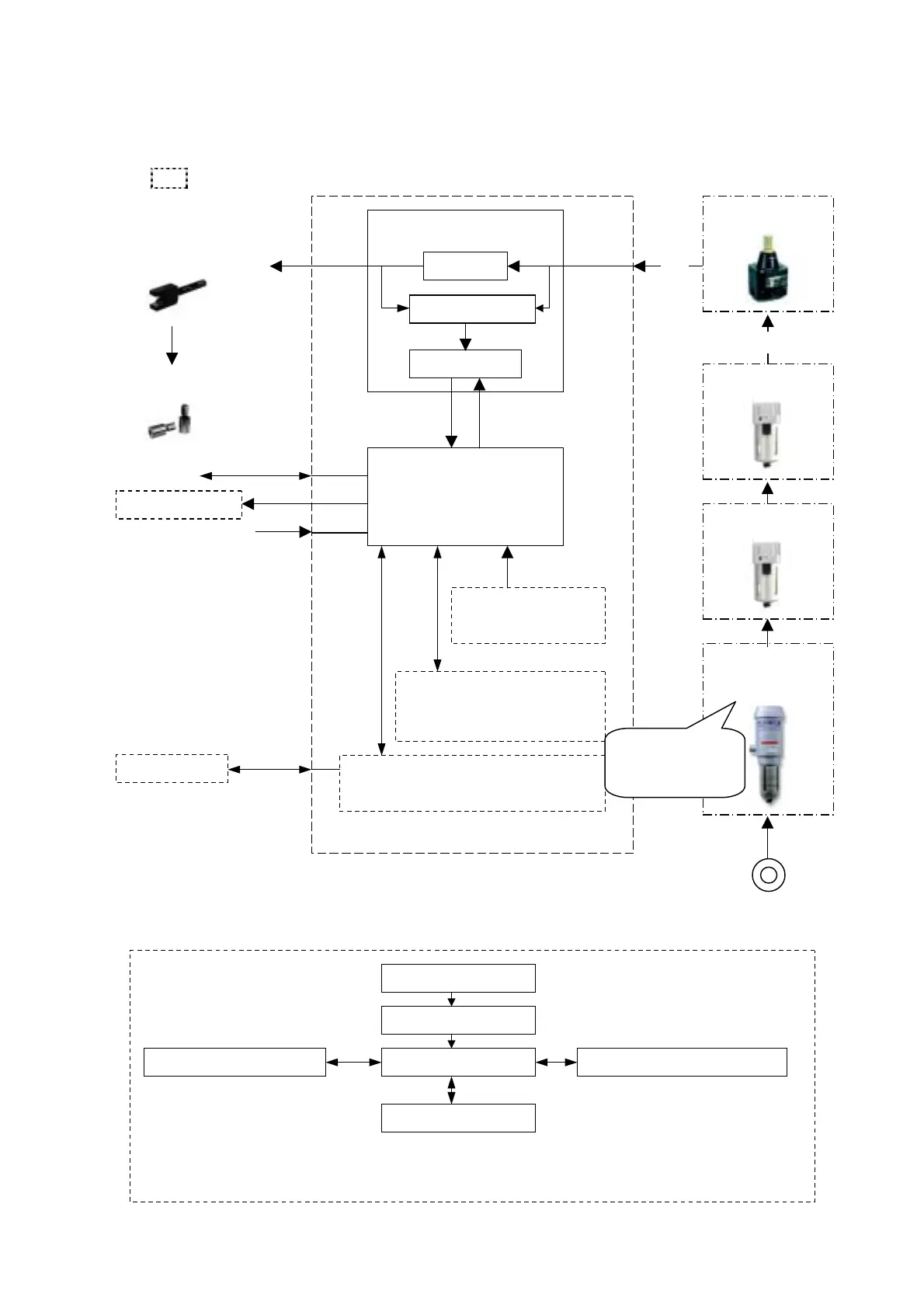
1.3 Block Diagram
(1) Structure
Arrow represents the direction of air and electric signal.
is optional.
(2) Operation flow
Shown below is the software operations diagram starting from turning on power.
Compressed air
purifier
Power ON
Initialization mode
Measurement mode Program switching mode
Setting mode
Master calibration mode
•
Measurement range selection
• Input of master value
• Input judgment limits
•
Master calibration
• Adjustment of detector
• Master calibration data clear
Program switching
Can save up to 10 kinds of
settings values
Reading of last setting values use
and master calibration data
• Confirmation of indicator ligh
(visual)
A/E Converter
CPU
Memory for saving settings
values and master calibration
data (good for 10 types)
Optional
DC I/O base
Memory for
operation software
Industrial pressure
Air circuit
Pressure sensor
Amp circuit
Parallel I/O
Work and master
Measurement
element/tool
Input Range switch
RS232C
Digimatic output
External input button
In case industrial
ressure contains
moisture and oil
Regulator
0.196±0.005MPa
0.3~0.7MPa
Mist separator
Filter