22 Unidrive M400 Quick Start Guide
Issue Number: 8
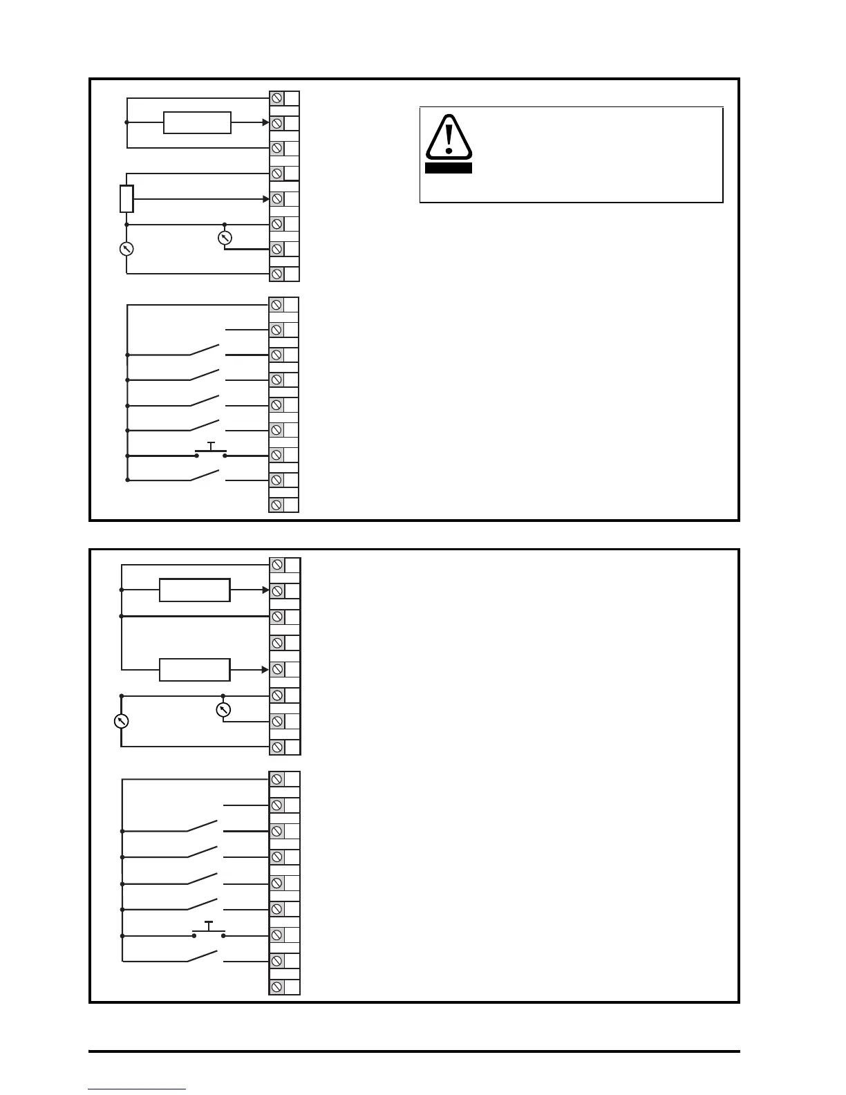
Figure 4-9 Pr 00.005 = Torque Control
Figure 4-10 Pr 00.005 = PID Control
* Refer to the Control User Guide.
1
2
3
4
0V
Current speed reference
input (AI 1+)
AI 1-
Torque reference
input (AI 2)
5
6
7
8
0V
Analog output 1
(motor frequency)
+ 10 V output
Analog output 2
(motor active current)
9
10
11
Digital output
(zero frequency)
Unassigned
12
13
14
15
16
17
Run reverse
Run forward
Torque mode select
+ 24 V output
Jog Forward
Unassigned
+ 24 V output
10k
Current speed
reference input
When torque mode is selected and
the drive is connected to an
unloaded motor, the motor speed
may increase rapidly to the
maximum speed (Pr 00.002 +10 %)
1
2
3
4
0V
PID feedback
input (AI 1+)
AI 1-
5
6
7
8
0 V
Analog output 1
(motor frequency)
+ 10 V output
Analog output 2
(motor active current)
9
10
11
Digital output
(zero frequency)
Unassigned
12
13
14
15
16
17
Run reverse
Run forward
PID enable
+ 24 V output
Jog Forward
Unassigned
+ 24 V output
4-20 mA PID
feedback input
0-10 V PID
reference input
PID reference
input (AI 2)
When Pr 00.005 is set to Pid, the following
parameters may need to be adjusted:
• PID proportional gain*
• PID integral gain*
• PID feedback invert*
• PID output upper limit (%)*
• PID output lower limit (%)*

 Loading...


