Chapter 5 Assembling and Connection of the System
22
5.1 Attaching the Product to an Epi Fluorescence Attachment
Attach this product to an epi fluorescence attachment that has a mount compatible with this product.
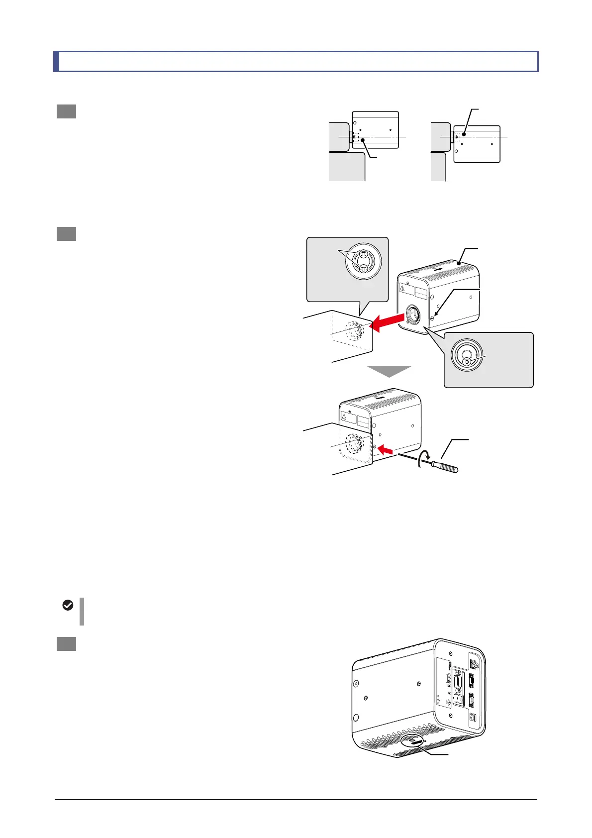
1 Decide the mounting orientation.
This product can be mounted rotated 180
degrees around the optical axis of the
light-emitting hole.
Check the space above and below the
mounting position and attach the system in
either of the orientations shown in the figure to
the right so as not to interfere with other
devices or cables.
Selecting the mounting orientation
2 Attach this product to a mounting section
of an epi fluorescence attachment.
In this product, the LED light-emitting hole
itself serves as a coupling to a dedicated
mount.
(1) Use a hexagonal wrench or Allen wrench
that is 2 mm across flats to loosen the
fixing screws to the sides of the
light-emitting hole.
There is a fixing screw on each side.
(2) Fit the anti-rotation pin on the light-emitting
hole into the groove on the mounting
section of the epi-fluorescence attachment,
and attach this product to the mounting
section.
Push it in to the limit position.
(3) Use a hexagonal wrench or Allen wrench
that is 2 mm across flats to tighten the
fixing screws to the sides of the
light-emitting hole to fix it in place.
There is a fixing screw on each side. Normally,
tighten both fixing screws.
Note that this product can be fixed properly by
tightening either the left or right fixing screw.
Access to either of the fixing screws may not
be allowed depending on the device to be
connected. In this case, fix the system by
tightening one of the fixing screws.
Attaching and fixing this product to
an epi fluorescence attachment
Cautions when attaching the product
Attach this product so that either of the vents on the top and bottom of this product faces up.
3 If necessary, attach a pillar on the bottom o
this product.
This product is provided with an M5 x 8 mm
tapped hole on each of the top and bottom
surfaces. Attach a pillar, etc. if necessary.
Depending on the attachment condition of the
illumination device, attaching a pillar is
required to prevent overweighing the
epi-fluorescence attachment or its connection
section.
D
-
LEDI
4N75
INSPECTION
EQUIPMENT
R
-
R
-
NEc
-
SD
-
LEDI
INPUT
12VDC , 3.3A
830001
This device compl ies with Part 15 of the FCC Rul es.
Operation is subj ect to the following t wo consitions :
(1) this device may not cause harmful interference, and
(2) this device must accept any interference received,
including inter ference taht may caus e undesired opera tion.
CAN ICES-3(A)/ NMB-3(A)
MADE IN JAPAN
TOKYO JAPAN
USB
REMOTE CONTROL
DC
TRIGGER
Place to attach a pillar
Optical axis is in
the lower side.
Optical axis is on
the upper side.
The vent
faces upward.
Mounting section of the
illumination device
Loosen the
fixing screws
(on both sides)
Tighten the
fixing screw
(Tightening only
one side can fix
the system)
Groove
Light-emitting hole
nti-rotation
pin
Pillar-attaching tapped
holes (M5 x 8 mm)