Chapter 5 Assembling and Connection of the System
26
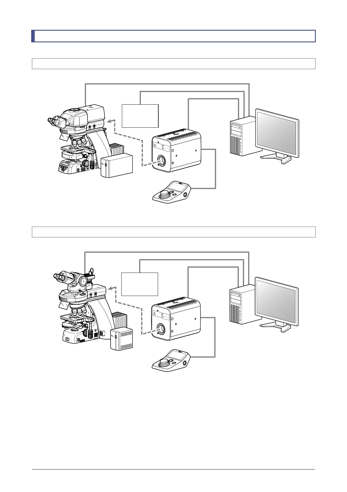
5.5 System Configuration Diagram
5.5.1 Ni-E + NI-CTLA System Configuration
IN
ND
8
ND
32
NCB
1
1
OUT
1
2
A
λ
F. STOP
A
.
ST
OP
EX. ADJ
2
3
4
5
6
5
0
60
7
0
PUS
H
ON/OFF
S
E
L
E
C
T
Fn
Man
ufactur
er
:
NIKON
C
OR
POR
AT
ION
Sh
i
n
agaw
a Inte
r
city T
o
w
er
C,
2-
1
5-
3
, Konan
, Minat
o-
ku, T
okyo
1
08-
6
290 Jap
an
Impo
rter
in the
Eur
o
pean
Economic Ar
ea:
E
C
RE
P
N
IK
O
N
IN
S
TR
U
ME
N
T
S
EU
R
OP
E
B
.V
.
T
r
ipolis
100, Bu
r
ge
r
we
eshuispad
101,
10
76 ER
Amster
dam
, T
h
e N
e
th
er
l
an
ds
WAR
NING
RISK
G
RO
UP3
A
VE
RTISSEMENT
GRO
UPE D
E RISQUE3
IEC 6247
1
5.5.2 Ni-U + NI-CTLB System Configuration
POWER
J
A
P
AN
69
6
00
1
N
I-
C
U
D
ND
8
ND
32
NCB
11
OUT
IN
F.
S
T
O
P
A
. S
T
OP
EX
.
AD
J
2
3
4
5
6
PUS
H
ON/OFF
S
E
L
E
C
T
Fn
Man
ufactur
er
:
NIKON
C
OR
POR
ATION
Sh
i
n
agaw
a Inte
r
city T
o
w
er
C,
2-
1
5-
3
, Konan
, Minat
o-
ku, T
okyo
1
08-
6
290 Jap
an
Impo
r
ter
in the
Eu
r
o
pean
Economic Ar
ea:
E
C
RE
P
N
IK
O
N
I
N
S
TR
U
ME
N
T
S
E
U
R
OP
E
B
.V
.
T
r
ipolis
100, Bu
r
ge
r
we
eshuispad
101,
10
76 ER
Amster
dam
, T
h
e N
e
ther
l
an
ds
WAR
NING
RISK
G
RO
UP3
A
VE
RTISSEMENT
GRO
UPE D
E RISQU
E3
IEC 6247
1
Ni-E main body
• Contact arm (NIE-CAM)
• Motorized fluorescence cube turret
(NI-FLT6-E)
• Control box A (NI-CTLA)
NIS-Elements (PC)
D-LEDI
Remote control pad
DS Camera
Control Unit
USB
USB
USB
Ni-U main body
• Contact arm (NIU-CAM)
• Motorized fluorescence cube turret
(NI-FLT6-E)
• Control box B (NI-CTLB)
NIS-Elements (PC)
D-LEDI
Remote control pad
DS Camera
Control Unit
USB
USB
USB