Chapter 4 Connecting and Installing the Equipment
3 Connection Methods
- 12 -
(3) Connecting the Nikon 80i/90i Microscope
Connect the digital imaging head mounted on the 80i or the 90i microscope to the USB (H)
connector of the DS-U2. Be sure to use the USB cable provided with the microscope.
(4) When connecting external devices (trigger signal output devices)
Before connection, always turn off the DS-U2 and external devices.
When the DS-Qi1Mc or DS-Ri1 is connected, triggered capture from external devices is possible by
supplying trigger signals to the EXT. I/O connector.
If you are preparing your own external device, use a device that meets the following specifications.
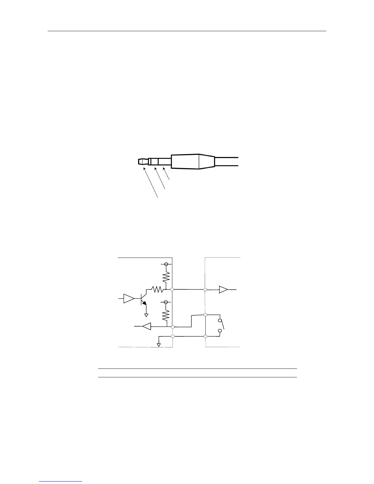
Connector: φ3.5 mm stereo pin jack
Functions
Pin 1: Trigger input
Pin 2: Read-out transfer timing signal (output)
* The TTL or LVTTL level signal can also be supplied through Pin 1.
In triggered capture, exposure is timed to the falling edge of the trigger signal. Settings configured
beforehand in the computer program for exposure time and camera gain are used. Captured
images are transferred via USB and displayed in the program.
The timing sequence of triggered capture is as follows.
Pin 3: GND
Pin 2
Pin 1
Operates when the switch is on (closed)
Pulse width: 1 ms or more
DS-U2
Pin 1
100Ω
4.7kΩ
Pin 2
Pin 3
External device
3.3V
3.3V
4.7kΩ