Chapter 3 Assembly
71
Chap. 3
Assembly
8
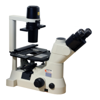
Connect connectors.
DSC
MODEL ECLIPSE Ci-E
USB REMOTE FOOT SWITCH
NIKON CORPORATION
TOKYO, JAPAN
100–240V~
1.0A
50/60Hz
MADE IN CHINA
This device complies with Par t 15 of the FCC
Rules. Operation is subje ct to the following two
conditions:
(1) this dev ice may no t cause harmful interfer ence,
and (2) this devi ce must accept any interfer ence
received, includi ng inte
rference that ma y cause
undes ired oper ation.
This Class A digital ap paratus complies with
Canadian ICES-003.
Cet appareil numérique de la classe A est
confirme à la norme NMB-003 du Canada.
930001
4N75
INSPECTION
EQUIPMENT
70
60
50
40
30
20
10
0
90
80
Hook
CAUTION
Make sure that the power is turned OFF before you
connect connectors shown below.
Connection of the remote control pad
Connect the remote control pad cable to a remote control
pad connector on the rear of the microscope.
Connection of DS-L4 or a PC
Ni Setup Tool
To connect a PC, Ni Setup Tool software must
have been installed in advance. For details on the
installation procedure, see the software manual fo
“Ni Setup Tool”.
Using a USB cable, connect the microscope to a USB
connector on the DS-L4 or the PC.
Refer to the “Ni Setup Tool” software manual or the
DS-L4 instruction manual to perform the necessary
configuration before use.
The microscope has two hooks on its rear, which can be
used to secure the remote control pad cable and the
USB cable.
Toggle control by external signals (Connecting a foot switch)
The Ci-E has a connector (FOOT SWITCH connector) for controlling the toggle function with an external
device. Connecting this connector to an external switch box, a toggle operation of the objectives is possible.
See the following for connection using the foot switch connector.
■ Connector pin layout
A 3.5 mm diameter mono mini jack (for audio
cables) is used for the connector on the device.
Connect using the figure on the right.
2
5
Connector circuit diagram
■ Toggle operation
To perform the toggle operation, press the toggle
pattern switch to select “toggle pattern 1” or
“toggle pattern 2”.
Under this condition, shorting Pin No. 2 on this
connector (FOOT-SW-IN) and Pin No. 5 (GND) or
inputting a LOW signal to Pin No. 2 allows the
microscope to perform the toggle
(The toggle does not repeat if shorting or signal
input continued).
If a momentary type switch is used, for example,
two nosepiece addresses set in toggle pattern 1 o
2 can be switched alternately each time the switch
is pressed.
FOOT SWITCH input signal
CMOS IC 74VHCT14
Input LOW: Toggle
Input HI: No operation
2: FOOT-SW-IN
toggle control
signal input
5: GND ground
GND
Control signal
C
+5V
33 k
1 k
Signal input
REMOTE
connector
FOOT SWITCH connecto
USB connector
Hook (same on the left)