Mounting of expansion PCB on CTS602 circuit board
If you connect an expansion PCB to the CTS602 circuit board, you will be able to use user selection 2.
Similar to user selection 1, user selection 2 allows you to override the functions of the unit via an
external signal from a potential free contact.
In addition, when activating user selection 2, the control system gives an output signal.
User selection 2 has a higher priority than user selection 1. It can be used in the same manner as user
selection 1.
The expansion PCB also enables activation of external space heating. It includes an alarm output and a
de-icing signal.
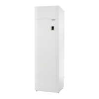
1. Remove the shown bus cable on the expansion PCB. 2. Install the large of the supplied print card holders in
the 3 holes of expansion PCB.
3. The expansion PCB must be connected to connector
CN9, and the caps must be mounted in the holes provided
for this on the CTS602 circuit board.
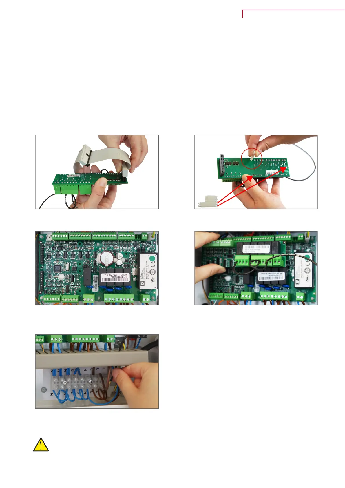
4. Mount the expansion PCB on the CTS602 circuit board.
5. Connect the wires as indicated on the electrical
diagram.
ATTENTION
The expansion PCB and the connections must be installed by an authorised electrician.
VP18 M2 (English) BY NILAN
21
 Loading...