NILES AUDIO CORPORATION – 1-800-BUY-HIFI – 305-238-437328
CONNECT THE LOUDSPEAKERS
CAUTION! ALL SPEAKER WIRE CONNECTIONS MUST BE MADE WITH THE
RECEIVER POWER OFF.
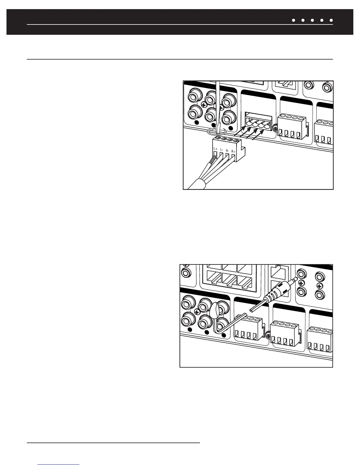
There are six sets of removable speaker wire terminals, one for each
zone. The terminals accept speaker wires up to 14 AWG in size.
Each terminal has four screw-down connections for speaker wire:
one positive (+) and one negative (-) for each speaker. Unscrew the
connection, insert the appropriate bare speaker wire, then tighten
fi r m l y
(Figure 12). Should a speaker output be shorted for some
reason, the power-on diagnostics routine in the ZR-6 MultiZone
Receiver will detect this short and display the specifi c output
experiencing the issue on the front panel LCD display. If a speaker
output is open, the amplifi er for that output is disabled by the power-
on diagnostics. Should a speaker be connected later, the amplifi er
for that output will be enabled during the next power-on sequence.
CONNECT THE EXTERNAL POWER AMPLIFIERS
If a zone is a particularly large area, or if high volume levels are required, it is suggested that Zones 4, 5, or 6 be augmented by an
additional stereo power amplifi er such as a Niles Systems Integration Amplifi er. The zone Preamplifi er outputs are selectable for variable
or fi xed output in the confi guration menu. The dedicated 12V output from each respective zone can be used to turn on the Systems
Integration Amplifi er power when the zone is active. The Global 12V output can be used to turn on the Systems Integration Amplifi e r ’ s
power when any zone is active.
CONNECT THE NILES IR MICROFLASHERS
Each Niles MicroFlasher (sold separately) connects into the
Flasher Outputs 2-6. The MicroFlasher portion is placed directly
over the IR sensor of the corresponding source component
(Source 2 for MicroFlasher 2, Source 3 for MicroFlasher 3, Source
4 for MicroFlasher 4, Source 5 for MicroFlasher 5, and Source
6 for MicroFlasher 6) and adheres with the included adhesive.
Remove the protective paper cover to expose the adhesive and
attach to the source component. A MicroFlasher is not used to
control the iPod. The iPod receives all control signals via the
30-pin connector cable.
NOTE: DO NOT CONNECT A MICROFLASHER TO THE HIGH OUTPUT
FLASHER PORT AS IT WILL DAMAGE THE MICROFLASHER.
CONNECT A HIGH OUTPUT FLASHER
A Niles IRB-1 High Output Flasher (FG1023) is used to control multiple devices. The mini-plug end of the IRB-1 connects to the "High
Output Flasher" output on the ZR-6 (the ZR-6 is shipped with a red plastic plug blocking this jack to prevent accidental connection of a
MicroFlasher. Remove the red plastic insert by pulling it out from the jack). The IRB-1 should be positioned to provide IR transmission to all
source components.
SYSTEM INSTALLATION
"4)&
0VU
;0/&
;0/&
;0/&
13&".10651654
ææ.JO
4QFBLFS0VUQVUT
$MBTT8JSJOH
ææ.JO
4QFBLFS0VUQVUT
$MBTT8JSJOH
ææ.J
4QFBLFS0VU
$MBTT8JSJ
Figure 13. Connecting IR Flashers to
ZR-6 MultiZone Receiver
ZR-6 MULTIZONE RECEIVER SYSTEM INSTALLATION
Figure 12. Connecting Loudspeakers to ZR-6
MultiZone Receiver
0VU
;0
;0/&
;0/&
13&".10651654
ææ.JO
4QFBLFS0VUQVUT
$MBTT8JSJOH
æ
4QFBLFS
$MBTT
ææ.JO
4QFBLFS0VUQVUT
$MBTT8JSJOH
 Loading...