Hopper System 113Service Manual – Advance 7765 / Nilsk CR1500
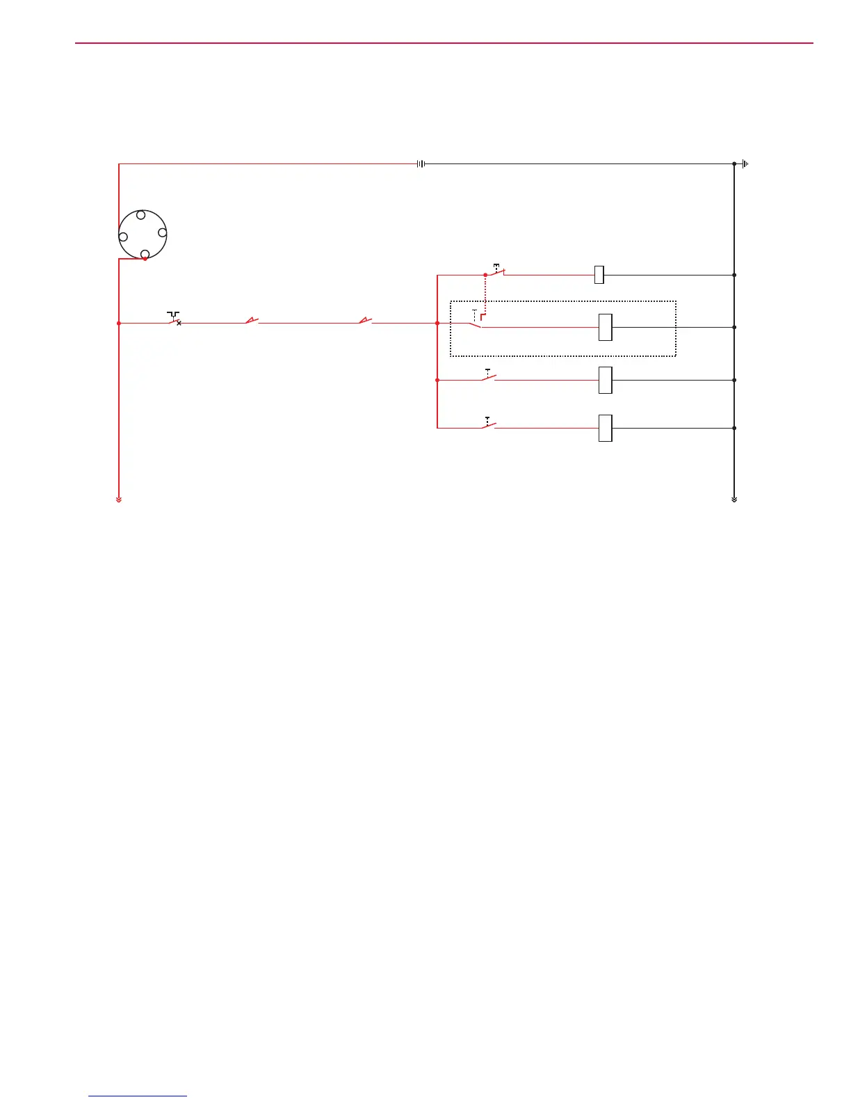
Hopper System Wiring Diagram – Variable Dump Machine
Electrical Circuit Description – Variable Dump Machine
The only electrical components associated with the hopper system are the Hopper Switch and the Hopper Door
Switch. Both of these “whisker” switches must be closed in order to get positive voltage to the Shaker Motor
Switch, Dust Control Switch, Main Broom Switch and Side Broom Switch.
Hopper Switch Hopper Door Switch
(Held Closed by Hopper) (Held Closed by Door)
7
B-
R1
Shaker Relay
Dust Control Solenoid (1)
8535 46
15
1557
15
86
1
Side Broom
Switch
2
1
Main Broom
Switch
2
1
Dust Control Switch
Option
2
3
37
1
Shaker Motor Switch
2
Main Broom Solenoid (2)
38
Side Broom Solenoid (5)
39
15
B-
7
7
CB6
15 A
137
2C CN.O. N.O.
1
Battery 12 VDC
+
-
Bat.
Ignition
Switch