Hopper System 114Service Manual – Advance 7765 / Nilsk CR1500
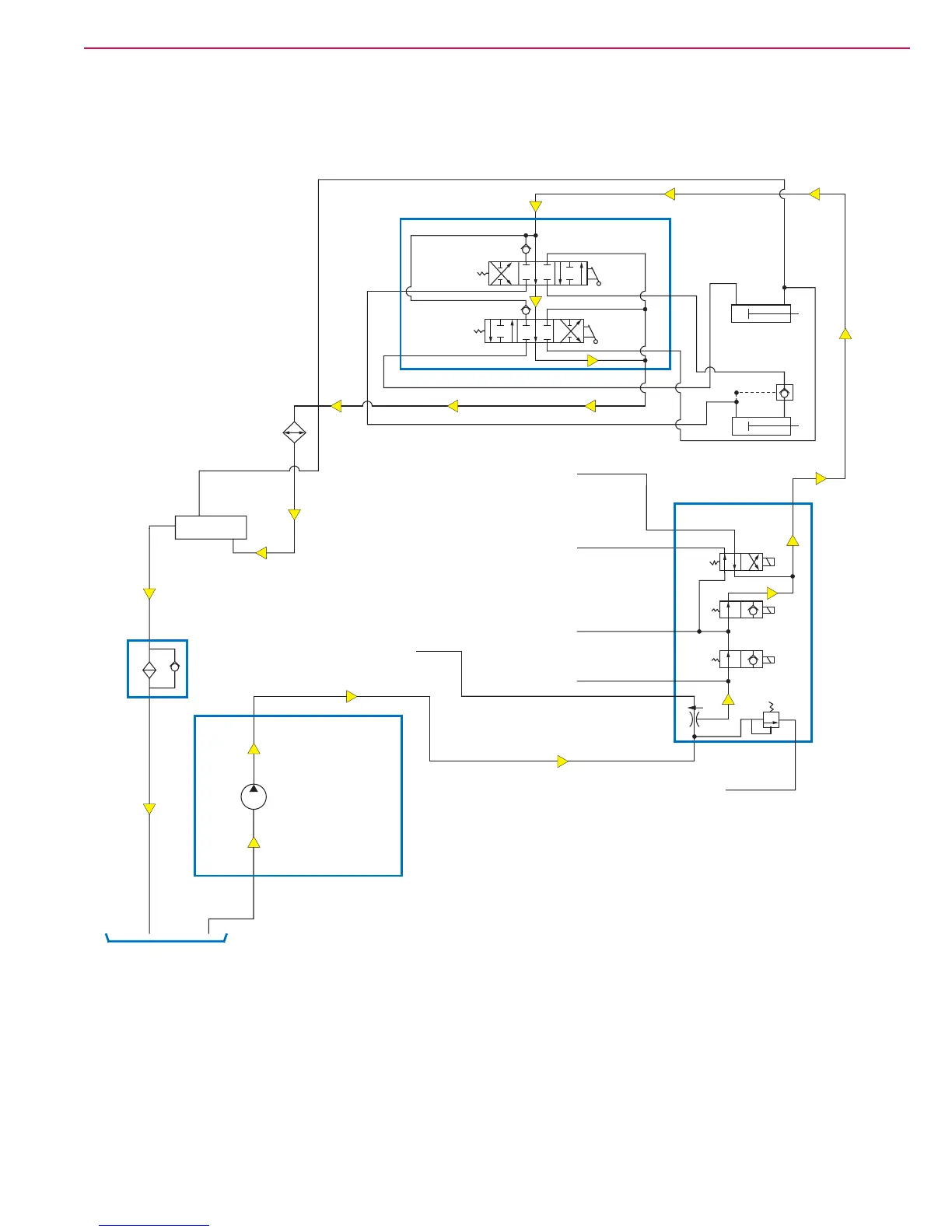
Hopper System Hydraulic Diagrams – Variable Dump Machine
Hopper Control Valves in Neutral Position
The hydraulic oil ows from the Auxiliary Pump, through non-priority leg of the priority ow divider, then
through the Main Control Valve to the Hopper Control Valve. Note that the oil will take this path regardless of
whether the Main Broom, Dust Control and Scrub Brush Motors are on or off.
When the Hopper Dump Cylinder Valve and Hopper Lift Cylinder Valve are in the neutral position, the oil ows
through the Hopper Control Valve, then through the Oil Cooler, Return Block and Filter to the Reservoir. Note
that the hydraulic lines from the Dump Cylinder and the bottom port on the Lift Cylinder are “deadheaded” in
the Hopper Control Valve to hold the hopper and dump door in position.
Lift Cylinder
A
C
D
B
Dump Cylinder
To Scrub
Brush Motors
To Main
Broom and Dust
Control Motors
From Main
Broom and Dust
Control Motors
From Scrub
Brush Motors
.75
GPM
Main Control
Valve
P
P1
1
2
3
T
4
1.02
CIR
Return Block
Reservoir
Auxiliary
Pump
Out
Hopper
Control
Valve
In
Oil
Cooler
Filter
9.7 GPM
Main Broom
Solenoid (2)
Normal Rotation
Brush (4)
Reverse
Rotation
Brush (3)
To Side
Broom
Valve
Hopper Lift
Cylinder Valve
Hopper Dump
Cylinder Valve
To Return
Block
2500
PSI
Relief
Valve
T1