30 - FORM NO. 56043107 - Advolution
™
2710
/ UHR 70-1700
WHEEL DRIVE SYSTEM
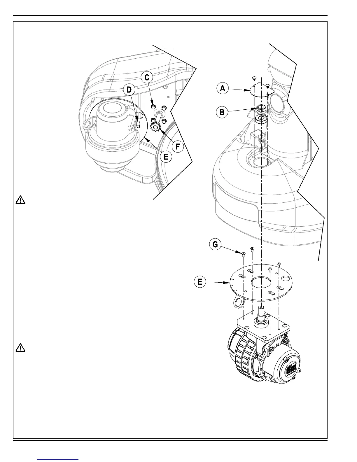
FIGURE 5
WHEEL DRIVE ASSEMBLY REMOVAL
WARNING!
Disconnect the battery pack by separating the battery connectors (7)
whenever servicing the machine.
1 Disconnect the battery pack by separating the battery connectors (7) located
underneath the drivers seat.
2 See Figure 5. Pull or pry off the Cover Plate (A) to access the Steering
Spindle Retainer Nut (B).
3 From underneath the front of the machine loosen the (4) steering column base
mount Screws (C). Service Tip: Use a 17mm socket wrench.
4 Observe and mark the drive motor wiring connections, then remove the two
large wires from their motor terminals.
5 Remove the P-Clamp (D) that fastens the drive motor wiring harness to the
Steer Plate (E).
6 Temporarily disconnect one end of the steering chain (remove the master
link) and separate the chain from the Steering Shaft Sprocket (F). NOTE:
Reassemble the master link (clip) back onto the end of the chain so that it is
not lost.
7 Remove the Steering Spindle Retainer Nut (B) with the use of a 1-7/16 inch
socket.
WARNING !
Never work under machine without safety stands or blocking to support the
machine.
8 Safely jack up the front of the machine 16 – 18 inches (40-45 cm) to remove
the wheel motor spindle assembly by carefully guiding it down through the
bottom of the frame opening and out from underneath the machine. NOTE:
Be careful not to damage the threads and bearing surfaces when dropping the
spindle through the frame when removing.
9 Inspect bearings and seal, replace as needed. Remove the (4) Screws (G) to
separate the Steer Plate (E) from the spindle weldment.
10 To make further service repairs see the Wheel Drive Motor Removal section.
11 Re-assemble in reverse order and tighten the Steering Spindle Retainer Nut
(B) just enough to eliminate any bearing free play.

 Loading...