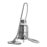
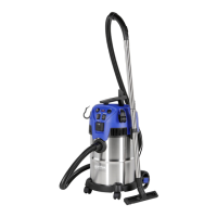
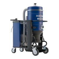
SOL 3 / SOL 5 W / BDC 3122 / BDC 3140 / E-VAC3000
9
03/2009
GB
[ NOTE ]
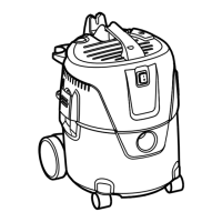
Ifthereisonlyadustdepositontheseparator(1)allow
thedusttodropthroughthecentralhole.
The separator (1) should rst be disassembled in order to be
perfectly cleaned:
■ Use the lever (2) to remove the lid (3) together with the
lter.
■ Unscrew the two screws (4) and remove it from the
container.
Replace the part if it is excessively worn. Assemble the
components in the reverse order of disassembly.
Vacuum cleaner disposal
Dispose of the vacuum cleaner in compliance with the laws in
force.
Wiring diagrams
Basic vacuum cleaner
Figure 17
1 Plug
2 Vacuum cleaner
3 Circuit breaker
Name Part
Code
SOL 3
BDC 3122
SOL 5 W
BDC 3140
E-VAC3000
Q1
Circuit breaker 8 391156 8 391157
Box for Q1 8 391052 8 391052
Wet vacuuming kit
Figure 18
1 Power supply
2 Transformer
3 Liquid sensor
4 Auto release
5 Vacuum cleaner
6 Circuit breaker
Name Part
Code
SOL 3
BDC 3122
SOL 5 W
BDC 3140
E-VAC3000
Q1
Circuit breaker 8 39915 8 39916
Handle for Q1 8 39954 8 39954
B1 Auto release 8 391142 8 391142
PR1 Pressure switch 8 40841 8 40841
F1 - F2 Fuse holder 8 39244 8 39244
TR1 Transformer 8 391050 8 391050
Motor cooling fan inspection and cleaning
Periodically clean the motor cooling fan to prevent the motor
from overheating, especially if the vacuum cleaner is used in
a dusty place.
Seal inspection
Figure 14
1 Hose
2 Hose
■ Hoses check
Make sure that connecting hose (1) is in a good condition
and correctly xed.
If the hose is damaged, broken or badly connected to the
unions, it must be replaced.
When sticky materials are treated, check for possible
clogging along the hose (2), in the inlet and on the bafe
plate inside the ltering chamber.
Scrape the inlet from the outside and remove the
deposited waste as indicated in the gure.
Figure 15
1 Gasket
2 Screws
3 Filtering chamber
■ Filtering chamber tightness check
If the gasket (1) between the container and the ltering
chamber (3) fails to guarantee tightness:
▪ Loosen the four screws (2) that lock the ltering
chamber (3) against the vacuum cleaner structure.
▪ Allow the ltering chamber (3) to lower down and
tighten the screws once it has reached the tightness
position (2).
The gasket (1) must be replaced if it is torn, cut, etc...
Replace the gasket (1) if the degree of tightness is still
not optimum.
Separator cleaning and replacement (if
equipped)
Figure 16
1 Separator
2 Lever
3 Cover
4 Screws
 Loading...