Construction
C
NEPTUNE 1&2_EN_Ver.2.1_45/2014
53
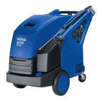
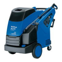
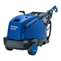
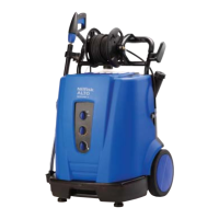
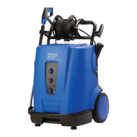
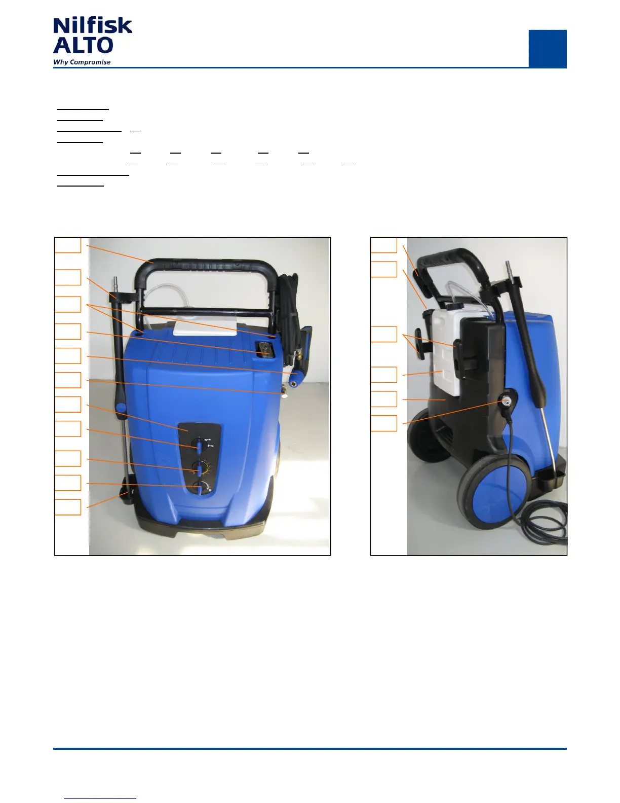
Fig.C2:NEPTUNE 2—26 Fig.C.1: NEPTUNE 2 - 26
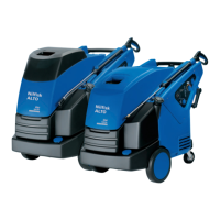
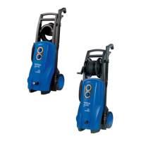
VARIANTS:
Neptune 1
Single phase: 1-22 EU
Neptune 2
Single phase: 1-22 EU, 2-25 GB, 2-26X GB, 2-26 EU, 2-26X EU, 2-26 SPECIAL EU, 2-26X SPECIAL EU.
Three phase: 2-33 EU, 2-33X EU, 2-33 NO, 2-33X NO, 2-41 EU, 2-41X EU, 2-30 SPECIAL EU, 2-30X SPECIAL EU
X vs. Standard : Hose Reel and Hose lenght 15m.
SPECIAL: 1400RPM motor/pump unit & without steam device
2.
1.
3.
4.
5.
9.
10.
11.
_ : These numbers refer to the theoretical total impact of spraying water calculated by the formula:
Impact = Q1 x √ P1 x 0.24 [ N ] P1 = bar. Q1 = l/min.v P1.
6.
1.
2.
3.
4.
5.
6.
7.
8.
1. Handle.
2. Lance holder, Top.
3. Cabinet lock.
4. Exhaust.
5. Ergo 1000.
6. Water outlet.
7. El-box lid with operation display.
8. Main switch.
9. Temperature Regulation.
10. Detergent Regulation.
11. Lance holder buttom.
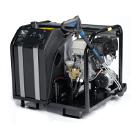
1. Hose holder.
2. Fuel filler.
3. Power cord holder.
4. Detergent tank.
5. Fuel tank.
6. Water inlet.
 Loading...