D
56
Function
NEPTUNE 1&2_EN_Ver.2.1_45/2014
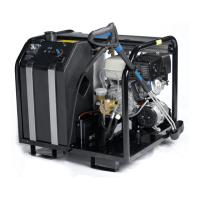
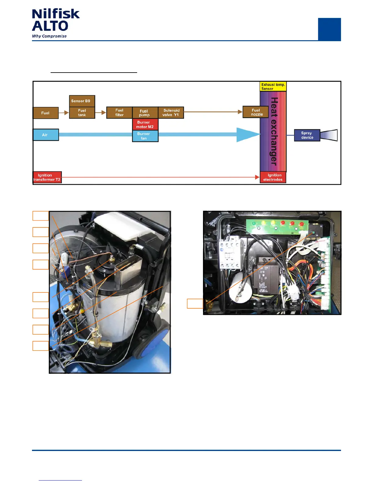
Heat system - Principal drawing
1
2
3
4
5
6
7
The single phase electrical burner moter (1) drives the fuel pump (2) and the burner fan (3). The fuel pump (2)
intakes fuel from the tank (8) through the fuel filter and conveys it, with the solenoid (4) activated, through the fuel
nozzle (5) into the heatexchanger (7). The burner fan (3) simultaneously adds the necessary air. The ignition
transformer generates the 12 kV high voltage for the electrodes. A spark is produced across the electrodes to ig-
nite the fuel/air mixture. The exhaust sensor (6) controls the exhaust temperature and cuts of the machine when
the temperature reaches 270 C. The switch (9) for exhaust sensor is placed in the E-box.
8
9
Fig.D.2. Heat system.
Fig.D.3. Heat system
Fig.D.4. Heat system
 Loading...