Sdasdasdsdfdsdcdscsdcdcd
cdcsc
Nitronic
NitronicNitronic
Nitronic
Mattenstrasse 11
CH – 2555 Brügg Tel. +41 32 373 70 70
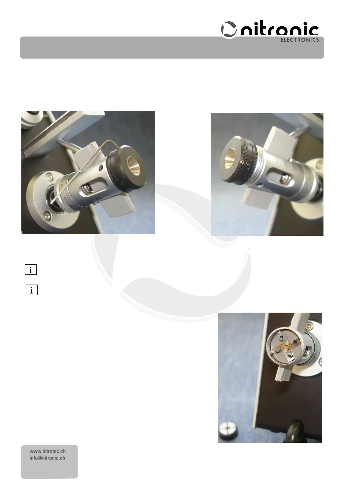
• Insert the position retainer corresponding to Fig. 6 in hat stripping head. For this, slide the big Allen screw near the
length scale, to the back. This procedure allows to easily insert the new blades.
• If the centering unit is blocked, loose the bright and small Allen screw.
• Loose the black and small Allen screw of the centering unit.
• Loose the entire centering unit and pull it out Fig.
7
.
Fig. 6 Fig. 7
Now you can see the four stripping blades Fig.
8
In order to avoid losing the very small stripping blades, we recommend that you put down a dark-colored,
smooth mat and use a pair of tweezers.
All four stripping blades must be changed at the same time in order to maintain a consistent stripping quality.
• Remove each stripping blade (8)
(8)(8)
(8) individually from the guide plate (9)
(9)(9)
(9).
..
.
• If necessary, carefully clean the guide plate (9)
(9)(9)
(9) with a dry brush
• Insert new stripping blades (8)
(8)(8)
(8) individually. As far as possible, align the
stripping blades accurately with the track so that the blades do not
subsequently jam.
• Insert the centering unit carefully, but do not yet tighten
do not yet tightendo not yet tighten
do not yet tighten
it
itit
it.
• Remove the position retainer.
• Set the diameter scale to 0.0mm (0.0 Inch).
Fig. 8