WWW.NORAC.CA
PRECISIONDEFINED
Page8
Visitwww.solutions.norac.caformoresystem
installationandtroubleshootinginfo.
5 HydraulicInstallation
Ensure all pressure has been bled from the system before disconnecting any lines or fittings.Hydraulic
pressurewillexistonthewingtiltcircuitsunlessthewingsarebeingsupportedbyothermeans.Thehydraulic
installation may be performed with the wings in transport position, resting on the ground or with the tilt
cylindersfullyextended.
Component failure due to oil contamination is not covered under the NORAC system warranty. It is
recommendedthataqualifiedtechnicianperformthehydraulicinstallation.
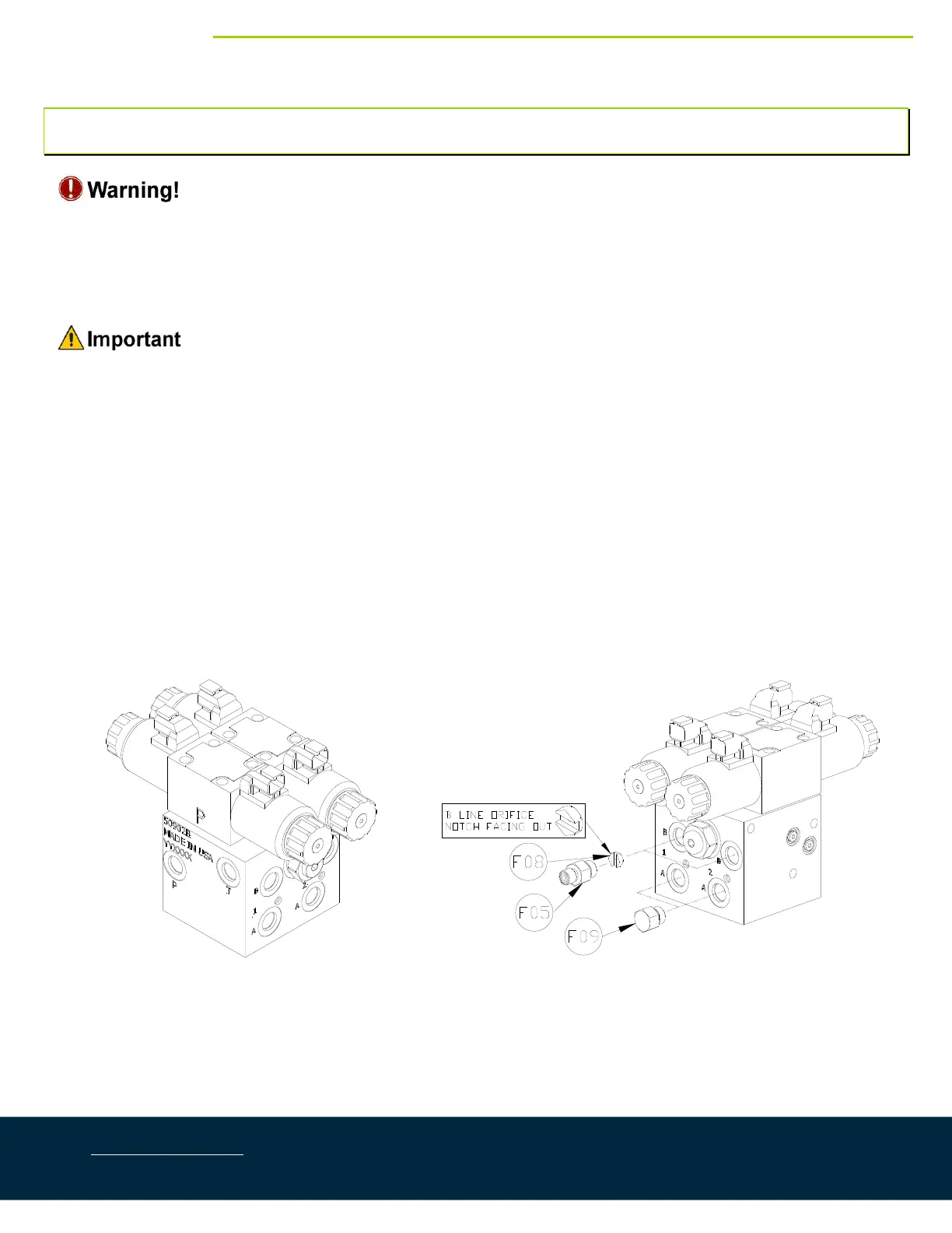
5.1. ValveBlockAssembly
1. Onacleansurfaceremovetheplasticplugsfromtheblock.
2. Installthe6MB‐6MJ(F05)fittingsintothe“P”and“T”ports.Tightento18ft‐lbs(24Nm).
3. Insertthetwoorifices(F08)intothe“B”portswiththenotchfacingoutward.
4. Installthe6MB‐6MJ(F05)fittingsintothe“B”ports.Tightento18ft‐lbs(24Nm).
5. Installthe6MBPplugs(F09)fittingsintothe“A”ports.Tightento18ft‐lbs(24Nm).
Figure4:NORACValveBlockDetails