WWW.NORAC.CA
PRECISIONDEFINED
Page16
Visitwww.solutions.norac.caformoresystem
installationandtroubleshootinginfo.
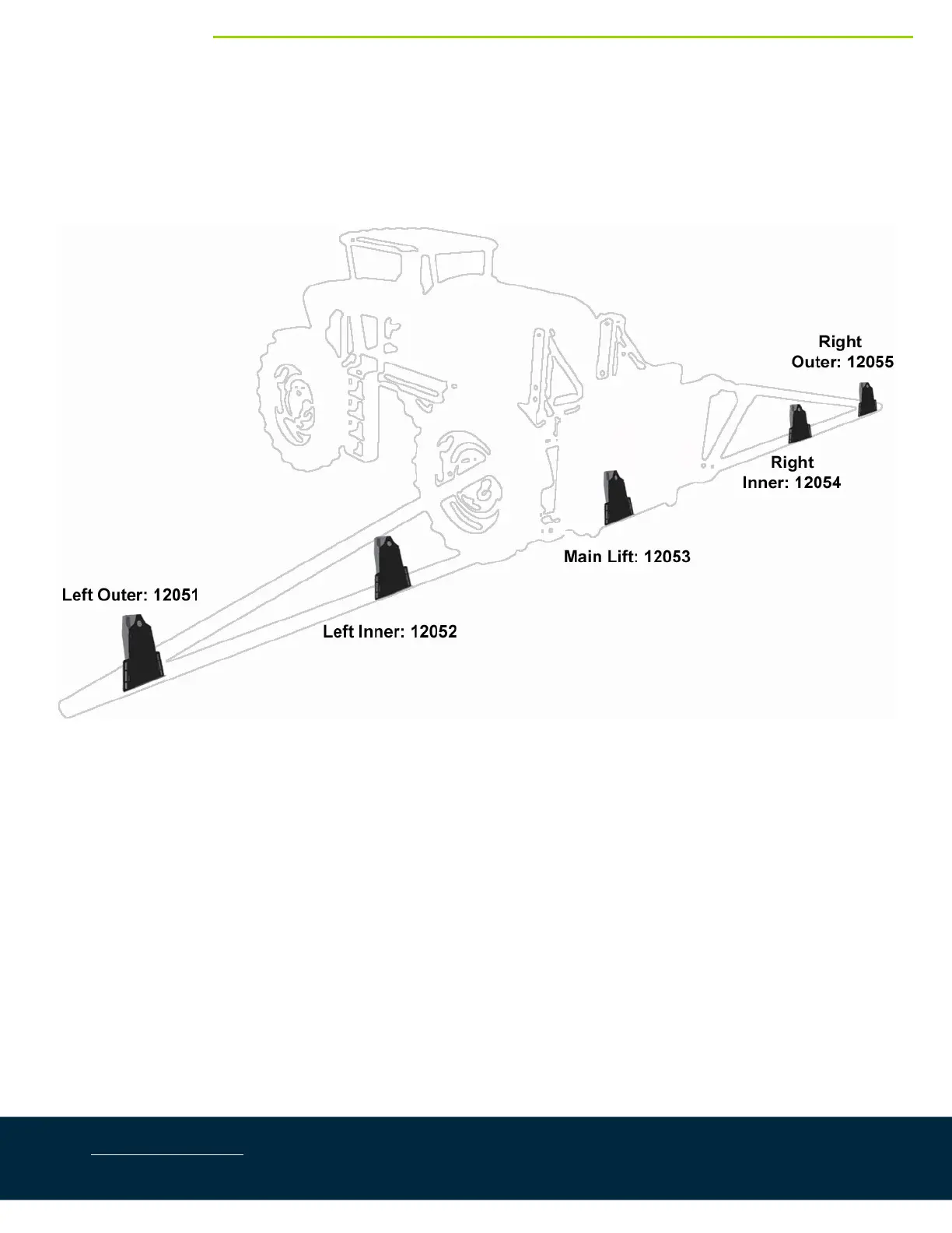
6.4.2. InstallationofaFiveSensorSystem(SevereTerrainOption)
WheninstallingtheMAXSensors™(E07),startwiththesmallestserialnumber ontheleft‐hand sideandproceed
tothelargestserialnumber ontheright‐handside.Eachsensorhasaserialnumberstampedonthesensor
housing.
Figure19:SensorSerialNumberArrangement
1. Thesensorbracketshouldbeorientedforward(aheadoftheboom).
2. MounttheouterwingsensorbracketsasdescribedinSection6.4.1,step2.
3. Mounttheinnerwingsensorbracketsontotheboomhalfwaybetweenthetipandcenterofthesprayer.
4. Steelboom:Usethe2x2x8spacers(B12)tomountthebracketonthe lowestpartoftheboom.Thespacer
mustbeplacedbetweenthelowestpartoftheboomandthebackfaceofthebracket.Theplateisplaced
behindtheboom.(Figure20)
NOTE: Thespacers(B12)arenotincludedinthiskit.