WWW.NORAC.CA
PRECISIONDEFINED
Page20
Visitwww.solutions.norac.caformoresystem
installationandtroubleshootinginfo.
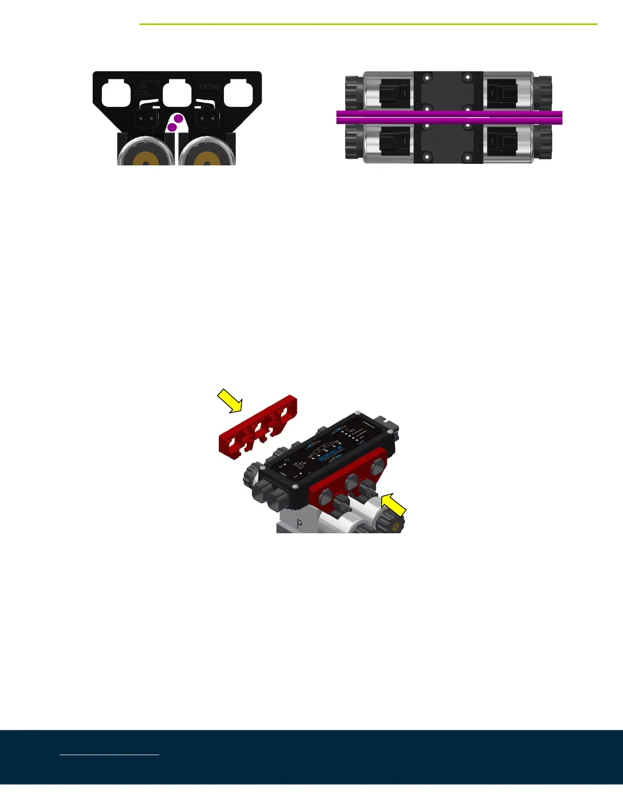
Figure28:CablesUnderMountingClips(SideView)
Figure29:CablesLaidAcrossValveCoils(TopView)
3. PlacetheHCM1(E01)betweenthevalvecoils.Orientthe6‐pinDeutsch(CANbus)connectorstowardsthe
“P”and“T”portswiththelargelabelandLEDsfacingup.
4. Slidethemountingclipsovertheconnectorsofthe HCM1andthevalvecoilconnectors.Thismayrequire
flexingtheplasticbracketslightly. Ensure theclipispushedovertheconnectorsfarenoughtoallowthe
clipstoengagebehindthevalveconnectors.
5. Connectthevalvecables(C10)to thevalvecoilsandtheHCM1.Thecableconnectedtotheleftconnector
(1,2)shouldbeconnectedtothecoil closestto the“P”and“T”ports.Thecableconnectedtotheright
connectorontheHCM1(3,4)shouldbeconnectedtothecoilfurthestfromthe“P”and“T”ports.
6. ConnectcableC12tothemainliftconnector(5,6)ontheHCM1.Teethecableintotheexistingmainlift
connection.
Figure30:HCM1andClipInstallation
7. Connectthetemperatureprobe(C11)totheHCM1(temp/9connector).Connectthetemperatureprobe
totheholelabelled“TP”onthevalveblockusingthesupplied3/8”x1/2”(9.5mmx25mm)bolt(Figure
31).
8. Insert4‐pinplugs(P01)intoanyunusedconnectorsontheHCM1.