WWW.NORAC.CA
PRECISIONDEFINED
Page21
Visitwww.solutions.norac.caformoresystem
installationandtroubleshootinginfo.
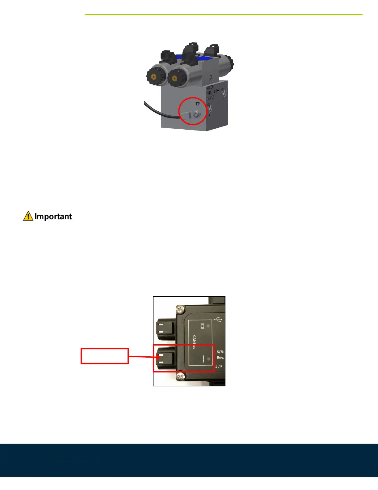
Figure31:ValveBlockwithTemperatureProbeInstalled
9. Connectthe12‐pinconnector oncableC20totheHCM1.TeetheconnectorsoncableC20intotheleft
up,leftdown,rightup,andrightdownfunctions.
10. Connectthe mainupconnectorsonC20 together.ConnectthemaindownconnectorsonC20together.
Ensurethatthemainupanddownconnectorswillnotinterfereorcatchonanything.Theseconnectors
arenotusedforthisinstallation.
Ensurethatallunusedconnectorsarepluggedwiththeplugsprovided.
7.2. BoomCablingConnections
1. Fastenthe8‐waycouplertotheboomwithcable ties.ConnectcableC02betweenthe8‐waycoupler(E11)
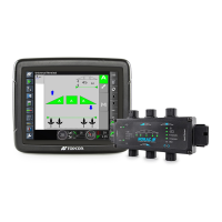
andthe6‐pinNORACbusconnectorontheHCM1.
Figure32:NORACBusLocation
2. Connectthemainliftsensortothe8‐waycouplerusingcableC01anda2‐waycoupler(E12).CableC01
anditemE12maynotbeneededifthe8‐waycouplerismountedcloseenoughtothemainliftsensor.
3. Insertthe6pinplugs(P03)intotheremainingreceptaclesofthe8‐waycoupler.
NORACBus