6
4.7 If the test stand is ever disassembled, it must be realigned when
reassembled. Use the alignment tool to check the alignment of the
test stand before each use.
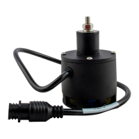
4.8 Inspect the sensor for visible damage. Inspect the transducer by
removing the foam and looking through the screen. The underlying
gold foil should be clean and free from tears, chemical deposits or
wrinkles. Ensure a clean foam disc is in the sensor before testing.
NOTE: It is advised that a new foam disc is used for sensor
testing.
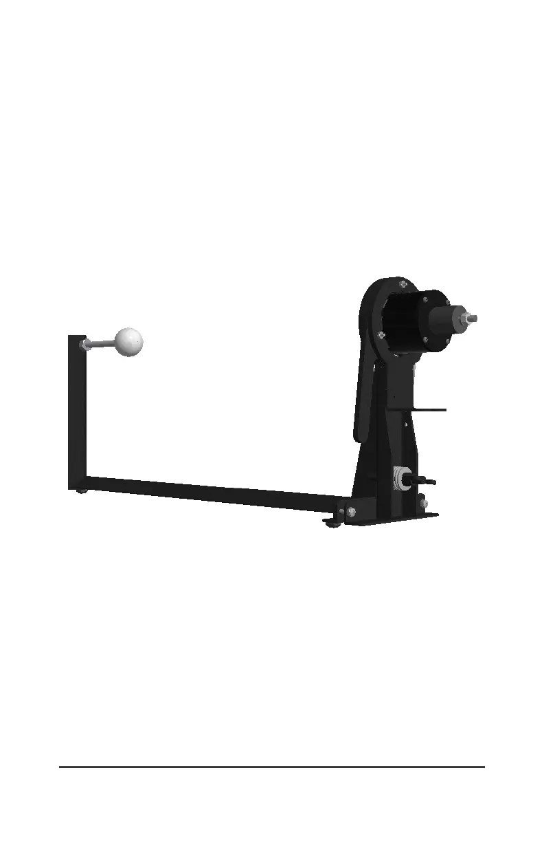
4.9 Mount the sensor into the sensor test stand. Press the handle
towards the stand and insert the sensor with the transducer facing the
golf ball as shown in Figure 4.
Figure 4: Sensor Mounted in Test Stand
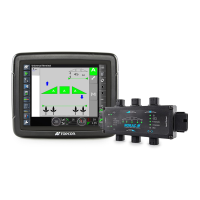
4.10 Attach the USB end of the USB-to-Serial Adapter to the computer and
ensure that the Serial end is attached to the Bus Monitor.
4.11 Connect the Bus Monitor’s Power connector labeled “To CANBus”
to the Bus Monitor Stand-Alone Power Cable connector labeled “To
Bus Monitor”.
4.12 Connect the banana plugs on the Bus Monitor Stand-Alone Power
Cable to a 12Vdc power supply.
4.13 The red banana plug must be connected to the positive terminal and
the black banana plug to the ground.
4.14 Switch the power supply on, check that the LED on the Bus Monitor is