10.4.3 User Manual Contents April 17, 2020
Firmware: 5.2.1 Page 102 of 142
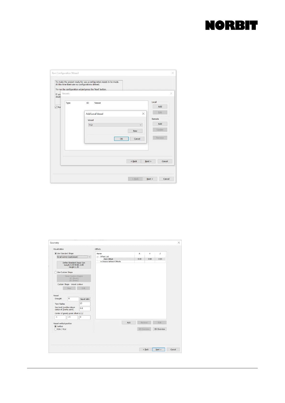
Step 3. Add New Vessel
Specify a name for the configuration (e.g. “Survey Vessel Pole Mount”) and on the next page add a
Local vessel which will contain all drivers and offsets.
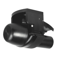
Step 4. Enter Offsets
On the Geometry page, define the shape of the vessel (only for display) and enter the Center of
Gravity offset as measured from the WBMS Reference Point. Leave the CoG Z field zero to keep
the setup simple, as the Sea Level offset is defined in relation to the CoG. Then enter the Sea Level
offset relative to the WBMS Reference Point. This should be a positive value.
If the optional iLiDAR is installed, add its offset to the list. This is the measured offset from WBMS
Reference Point to iLiDAR Reference Point. Refer to the iLiDAR manual for more details.