10.4.3 User Manual Contents April 17, 2020
Firmware: 5.2.1 Page 104 of 142
Step 6. Add Optional Devices
Optional drivers may be added for snippets or side scan data, true heave data, and LiDAR data:
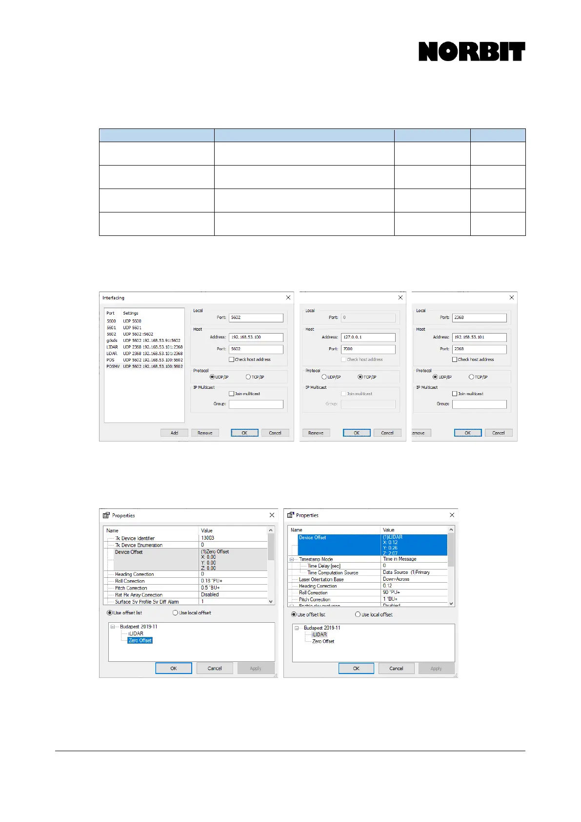
Step 7. Configure I/O Ports
Select each device on the Equipment list and click I/O Port to configure the interfacing parameters,
as per the tables in the previous sections.
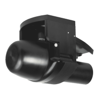
Step 8. Configure Device Properties and Apply Offsets
For each device on the Equipment list, click Edit to open the Device Properties. Here you must select
the offsets to apply, as defined previously on the Geometry setup. Recall that all applied offsets
should be zero, except the optional iLiDAR.
The patch test values, if known, may be entered in the device properties for the multibeam and
optional iLiDAR. They should be entered in the Roll Correction, Pitch Correction, and Heading
Correction fields.