Heading Alignment Wizard
A heading alignment must be performed when the iWBMS is first installed, or when one of the INS
sensors (IMU or GNSS antennas) is moved. The heading alignment determines the vector offset
from primary antenna to secondary antenna, and in doing so ensures proper alignment of the IMU
with the GNSS antenna pair.
If a heading alignment was not performed at the end of the INS Setup Wizard, select INS Tools >
Alignment Wizard and follow the on-screen instructions.
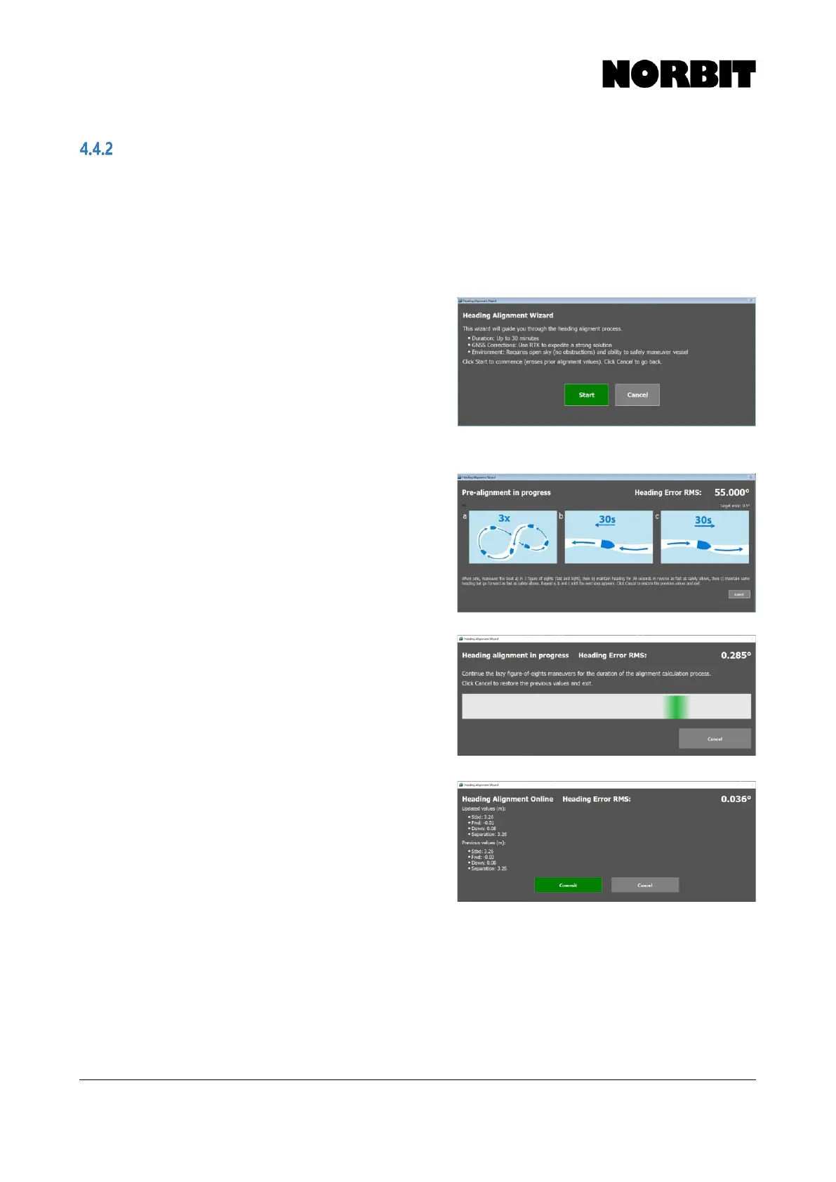
Step 1. With the Alignment Wizard open, press Start to
begin the calibration. The best results are
achieved using RTK GNSS, with a clear sky view,
away from tall structures that impede GNSS
performance. The installation must be completely
rigid and free from vibration. The primary antenna
offset must be accurately measured and applied
during the INS setup stage described in the
preceding section.
Step 2. Follow the recommended maneuvers during the
pre-alignment stage and observe the display as
the Heading Error RMS decreases from its initial
value of 55 degrees. Once the value drops below
the defined threshold (Target Error) and
stabilizes, the heading alignment begins.
Continue to maneuver the vessel until this
occurs.
Step 3. Follow the instructions and continue to perform
figure-of-eight maneuvers while the heading
alignment is in progress. The overall time to
complete the calibration depends on the size of
the vessel and the speed at which the maneuvers
are performed, as well as positioning quality.
Step 4. The computed results are displayed and are
unique to each installation. If the primary to
secondary antenna baseline was manually
measured beforehand, the calculated results
should be very similar. Check that the results are
sensible and select Commit to save the results.
NORBIT recommends performing a patch test
after the heading alignment.