Understanding Heading Alignment Results
Understanding the alignment results allows the user to verify the installation
and refine it if necessary.
The heading alignment establishes the baseline vector from primary to
secondary GNSS antenna. The X, Y and Z components of the vector from
primary to secondary antenna should closely match with the measured
values. Although it is not required to manually measure the values, it is
strongly recommended to do so as a check.
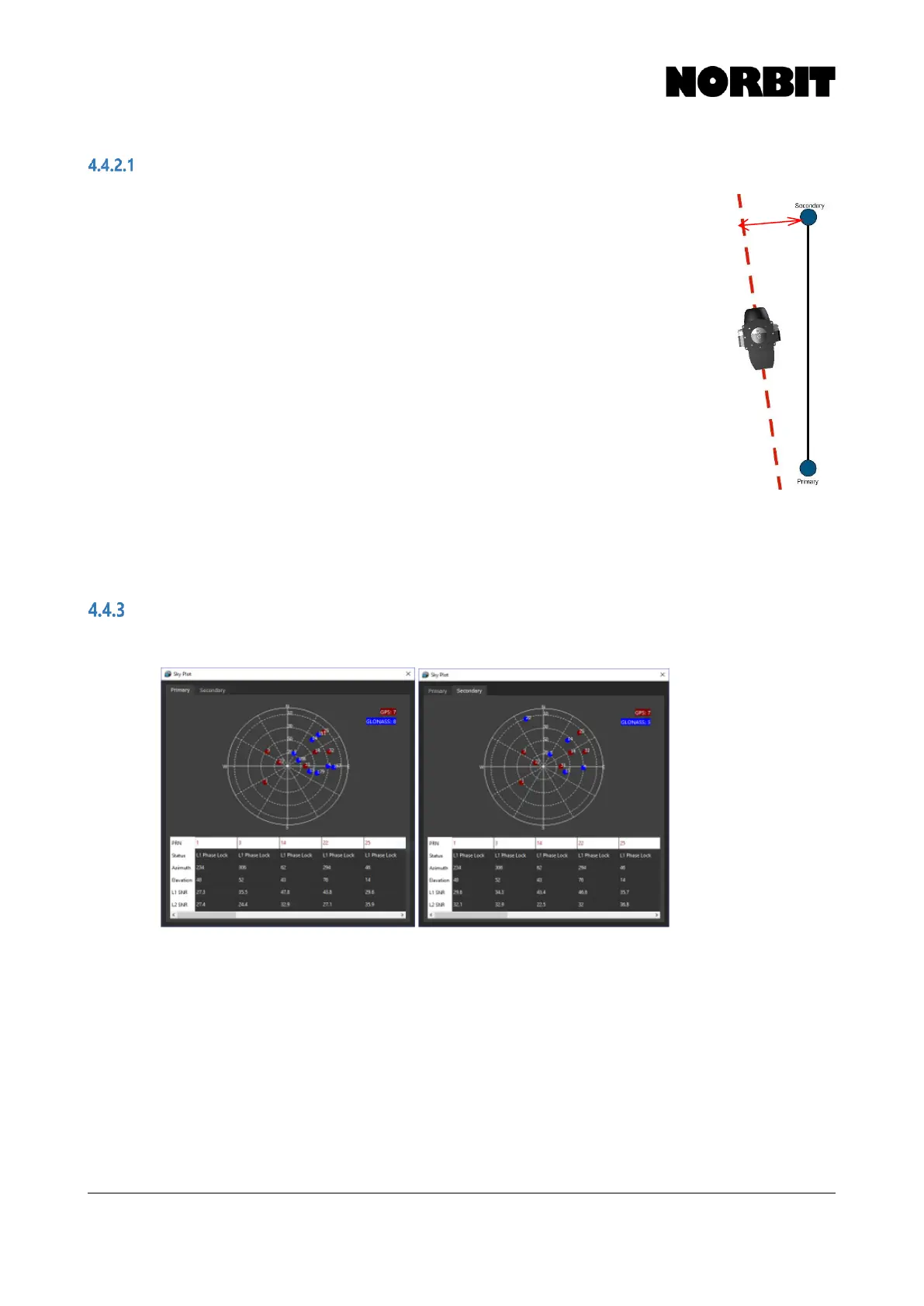
In this example, where the antennas are mounted along the X (fore-aft)
direction, the Y component of the heading alignment can be used to check
if the iWBMS is in alignment with the antennas. A small value in the Y
component indicates that the iWBMS is closely aligned with the antenna
orientation. A larger value indicates that the iWBMS is mounted with a yaw
offset with respect to the antennas, as shown in the image. This can be
used to bring the antennas and iWBMS into alignment either by adjusting
the mounting angle of the WBMS in the Z axis, or by adjusting the antennas.
By using an iterative process of adjustment and calibrations, the user can
achieve a high degree of alignment between the antennas and the WBMS.
The Z component is the vertical separation between the 2 antennas.
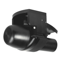
Sky Plot
The Sky Plot displays currently tracked satellites on the primary and secondary GNSS antennas.