10.4.3 User Manual Contents April 17, 2020
Firmware: 5.2.1 Page 47 of 142
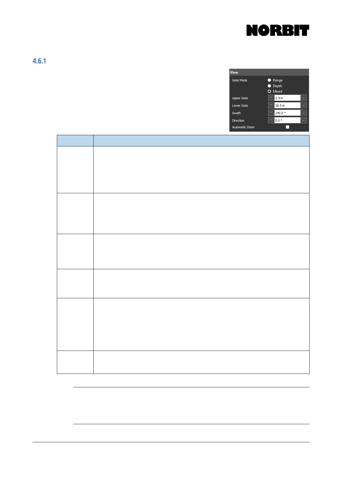
View
Most sonar control features can be found in the View menu. The
user may specify Gate Mode, the Upper and Lower Gates,
Swath angle and swath pointing Direction. The table below
describes each function in detail.
Sonar range is a function of the Lower Gate, angular Swath width
and swath pointing Direction. These parameters affect the total
distance bottom detections can be from the sonar, and the ping
rate is then determined by factoring in the speed of sound in water.
Allows for selection of manual gates by upper and lower depth (Depth mode), by upper and
lower range (Range mode) or by upper depth and lower range (Mixed mode). Depth gates
are suitable for most environments. Range gates are ideal for shallow water bank to bank
surveys, or when changing the Direction. A bottom search is performed between the Upper
Gate and Lower Gate independently for each beam. When Depth mode is active, changing
the Direction, or operating with a physically tilted head may drastically reduce the ping rate.
To avoid this, select Range or Mixed mode.
Sets the upper limit (minimum depth) for bottom detections. Change values by entering a
number and press Enter, by using up/down arrows next to the corresponding control bar, or
by interactively clicking and dragging the gate to the desired depth on the wedge. For most
surveys the minimum should be at least 1m to avoid false detections at the surface.
Minimum Value: 0.1m
Maximum Value: 599m
Maximum depth for calculating bottom detections. Change values by entering a number and
press Enter, by using up/down arrows next to the corresponding control bar, or by
interactively clicking and dragging the gate to the desired depth on the wedge.
Minimum Value: 1.0m
Maximum Value: 600m
User-defined total angular swath coverage. For typical harbor dredge surveys, this value is
normally set to 120-150°
Minimum Value: 5°
Maximum Value: 210°
Direction of swath pointing angle. 0° places the swath symmetrically around nadir. Under
normal operations, direction angle is dependent on swath width as no portion of the swath
may exceed the 179° allowable view. If the survey requires that depth be attained above the
sonar draft, the direction can be extended further up by first selecting 180° Swath. Next select
the desired Direction, then select the final desired overall Swath. Useful when surveying
slopes, shoreline or for mapping structures such as piers, bulkheads, etc. To maximize the
ping rate while using this feature, it is recommended that Range mode be activated and
regularly adjusted. Use of Depth mode may yield low ping rates when using this feature.
Makes the active portion of the wedge full screen. This ensures that detections are clearly
visible on the display, even when the range is very high. This is most effective when using
Adaptive Ping Rate with a large lower depth/range gate.
CAUTION: Steering Direction Limited in Equidistant Mode
In Equidistant mode, the swath angle cannot be increased such that any
part of the swath exceeds an 80° pointing angle, i.e. 10⁰ from horizontal (so,
a 160° swath with 0° rotation or a 120° swath pointed 20° is the maximum.)