9.9
Applanix INS Diagnosis
1. Check Timing: If there are no timing issues ignore
steps 1-3. If timing is incorrect, check the Primary and
Secondary GNSS indicators at the top of the GUI and
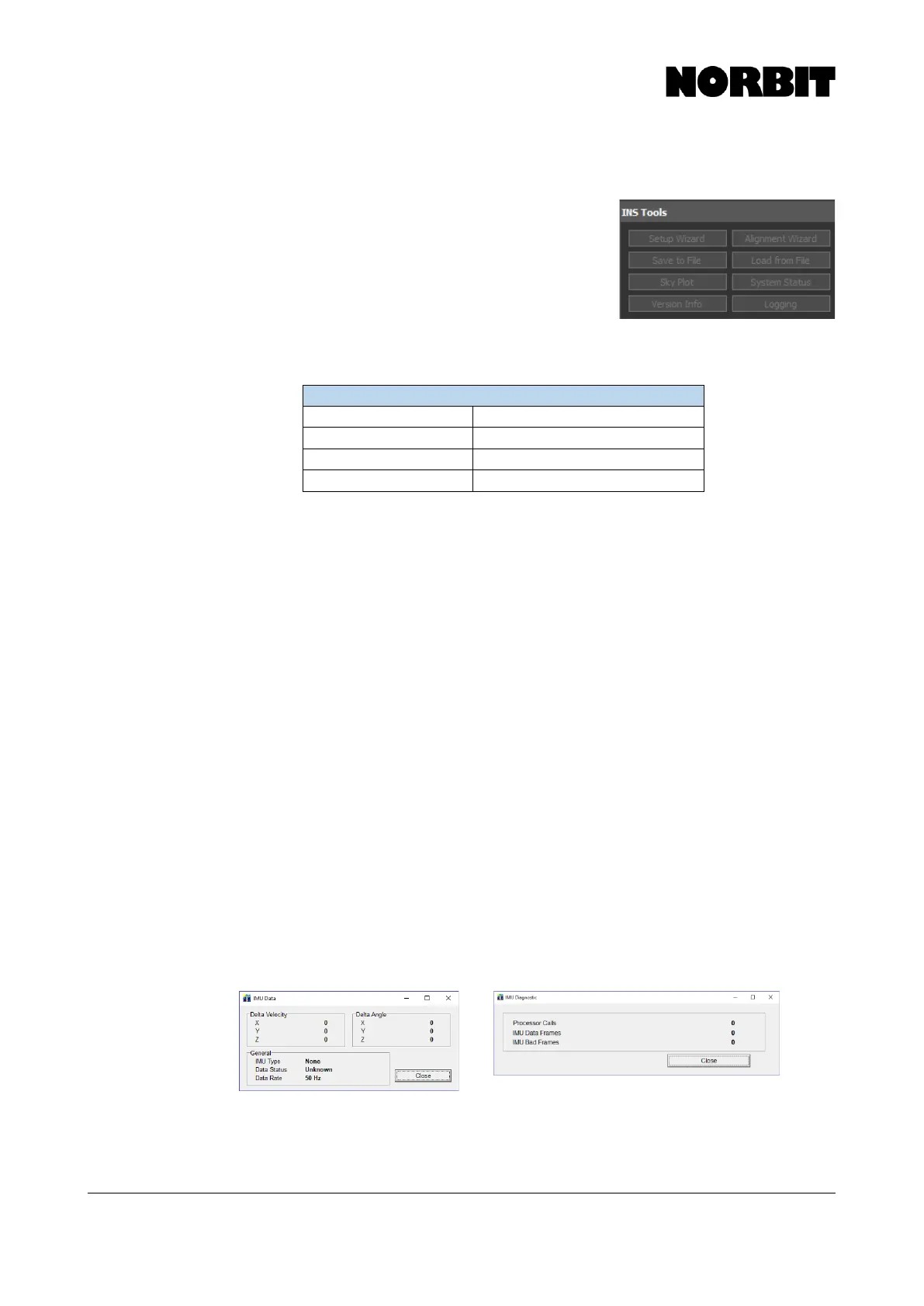
go to INS Tools > Sky Plot to check if any satellites are
detected, and if so, to what level of precision.
2. Confirm LED Status: Check PPS LED on the SIU. If
functioning correctly, it should blink at 1Hz. If satellites
are detected but the PPS LED is not blinking at 1Hz,
open POSView and check COM4 settings to check that it is outputting NMEA ZDA. For
LED indicator statuses, refer to the table below.
3. Inspect Pins: PPS LED is blinking at 1Hz, power off system and very carefully check for
bent IMU cable and SIU socket pins. If you find bent pins, contact NORBIT Support for
immediate instructions on how to fix them. If possible, please send pictures of the bent
pins to NORBIT Support. Also check cable and SIU sockets for dirt and other unwanted
materials that may interfere with the signal.
4. Physical Installation: For issues such as motion artefacts, let NORBIT support know if
any changes were made to the physical setup (e.g. if sonar/antenna pole was moved). If
possible, send pictures of the mounting configuration to NORBIT. The goal is to rule out
any wobble in the physical setup. Also, ensure that primary and secondary antennas are
no more than 2m apart. If they are not, heading accuracy may be compromised.
5. Check for Damaged Cable: If the check in #3 also passes, try gently turning and twisting
the sonar cable to see if a damaged cable is causing the issues. If it is, the symptom may
be reproduced by bending the cable at or near the damaged area.
6. Data Rate: In case of missing RTK signal:
a. If using NTRIP, check the internet connection and the correct COM port to use in Windows
Device Manager. Verify NTRIP login credentials, IP address, etc. Check Corrector type
and verify that baud rates specified in NTRIP match baud rates in the NORBIT GUI INS
Setup Wizard.
b. If using a rover, if no RTK signals are received, check that the radio is transmitting, and
that the receiver is tuned to the correct frequency and is functional. Verify that baud rates
and corrector types match.
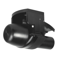
7. Screenshots: If the sonar is detected but the IMU is not, or an IMU Failure error is
displayed, check cable sockets for bent pins. If all pins look fine, power the system on,
open POSView and send screenshots of the main POSView display, as well as the
following: