Installation and Owner’s Manual 27
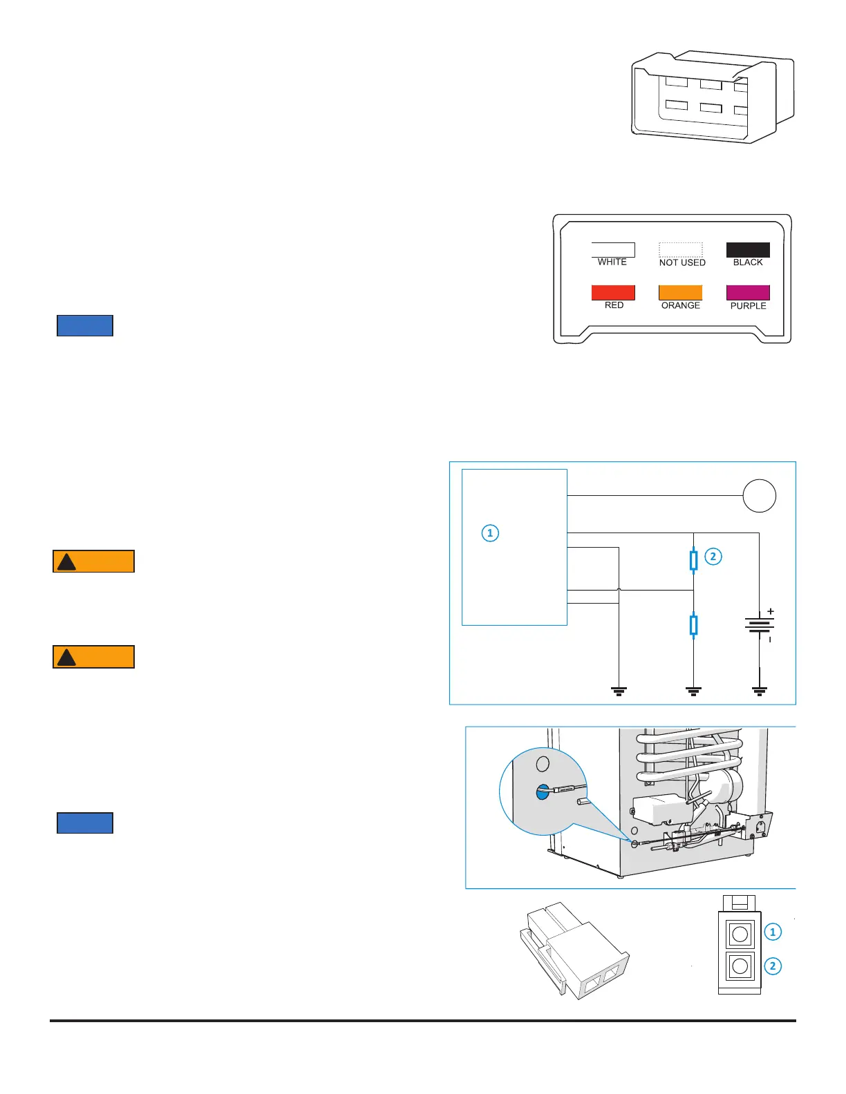
2. Install a fuse in DC power supply wires between the battery and the refrigerator:
- Put fuse as close to the battery as possible.
3. Connect the DC power supply wires:
These models have 2 connection points to prevent the battery from being discharged by the
refrigerator when the engine is not running.
High current supply red cable (+) and white cable (-) for heating element. Only turned on if
signal on D+
Low current supply purple (+) and black (-) for electronics.
D+ signal orange, + when engine runs
Use Stocko / Tyco / Amp 6-pole housing, or equivalent, with Lear connectors, or
equivalent, wired as shown.
Do not use the chassis of the refrigerator or the vehicle frame as one of
the conductors. Attach the DC power supply wires only to the battery
and the DC power cord of the refrigerator.
NOTICE
Art02350
TYCO / AMP 280314
TYCO / AMP 180906
Art02370
Connect the Electrical Components- 2-way Option
When the 2-way option is connected, the 12V DC power supply will be deactivated and only the gas and AC power supply are
available. To use the 2-way option, connect the wiring according to this diagram. (See Art02752) The 12V connector to the power
control board is provided by Thetford. A cable bridge will need to be done by the OEM.
Connectivity
To connect the refrigerator to the central board of the vehicle,
use the CI-bus protocal (please refer to: www.civd.de).
Any error message coming from the
refrigerator and shown on the master
display, should not distrub the driver. For
example : lights and/or sounds coming
from the master display while driving.
There is no load dump protection circuit
present on the CI-bus refrigerator
electronics. Thetford requires that a load
dump circuit (which complies with the
relevant regulations) is installed on the CI-
bus master if the refrigerator is connected to
the CI-bus.
The CI-bus connection point is located at the rear of the refrigerator.
(See Art02753)
NOTICE
CI-Bus connection is not available for models with a
battery pack.
CI-bus connector plug on refrigerator:(See Art02755)
Mini-Fit Jr. connector (male) supplier Molex PN 39012020, cable
length; 90mm.
CI-bus vonnector plug counter part: (See Art02754)
Mini-Fit Jr..Mini Fit Jr. Connector (female) supplier olex, Pn 39012021
ENG RUN
LC+12 VDC
LC GND
HC+12 VDC
HC GND
Vehicle
ba�ery
R1
47kΩ
R2
10kΩ
GNDGND
M
D+ Engine run
GND
+12VDC
+2VDC
WARNING
!
WARNING
!
ART 02753
ART02755