3. Storage, Preparation,
Installation
-18- B1000 www.nord.com
I Gear coupling (BoWex
), one-part
II Gear coupling (BoWex
), two-part
III Gear coupling (BoWex
), two-part with spacer bush
IV Claw coupling (ROTEX
), two-part
V Claw coupling (ROTEX
), two-part, observe dimension B:
Standard helical gear unit: SK0, SK01, SK20, SK25, SK30, SK33 (2-stage)
SK010, SK200, SK250, SK300, SK330 (3-stage)
IEC size 63 IEC size 71
Dimension B (Fig. 3-12V) B = 4.5mm B = 11.5 mm
VI Claw coupling (ROTEX
), two-part with spacer bush
3.10 Retrospective paintwork
Attention!
For retrospective painting of the gear unit, the radial seals, rubber elements, pressure venting
valves, hoses, type plates, adhesive labels and motor coupling components must not come
into contact with paints, lacquers or solvents, as otherwise components may be damaged or
made illegible.
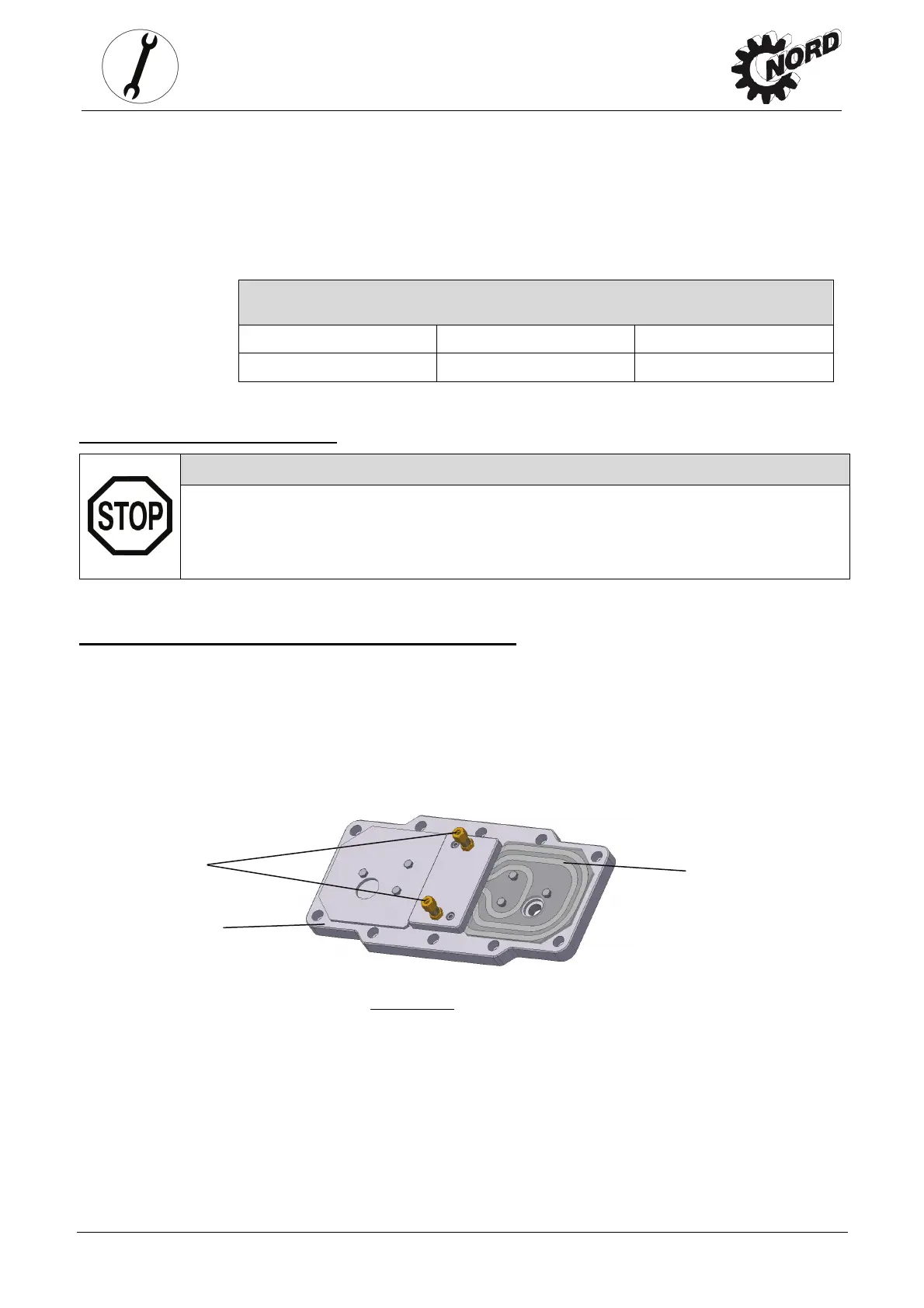
3.11 Fitting the cooling coil to the cooling system
Cutting ring screw threads (see Item 1, Figs. 3-13) are located at the casing cover for the
connection of a pipe with an external diameter of 10 mm according to DIN 2353. Remove the
drain plug from the screw neck prior to assembly to avoid any contamination of the
cooling system. The screw necks should be connected with the coolant circuit, which must be
provided by the operator. The flow direction of the coolant is irrelevant.
Make sure not to twist the screw necks during or after assembly as the cooling coil may be
damaged (see Item 3, Fig. 3-13). You must ensure that no external forces act on the cooling coil.
Figure 3-13:
Cooling cover
1
2
3
 Loading...