Do you have a question about the Nord Drivesystems B 1050 Series and is the answer not in the manual?
General safety advice, risks from improper use, and qualified personnel requirements.
Specifies that products must be used as per documentation and instructions are essential.
Guidelines for electrical installation, compliance with regulations, and EMC.
Precautions after power disconnection and before touching components.
Read manual carefully, keep it near the unit, NORD liability disclaimer.
Defines DANGER, WARNING, CAUTION, NOTICE, and Information symbols and their meanings.
Detailed safety measures, potential hazards, and required protective actions.
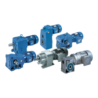
Lists helical and helical bevel gear unit types and their designations.
Instructions and warnings for safe transport of the gear unit, avoiding hazards.
Guidelines for short-term storage of gear units, including temperature and humidity.
Importance of checking the type plate for correct data and ensuring legibility.
Critical steps for safe installation, including load, burns, and anchoring warnings.
How to fit the gear unit onto a hollow shaft using a puller to avoid damage.
Instructions for connecting external cooling systems, including diagrams and explanations.
Guidelines for installing torque supports to avoid damage and ensure correct function.
Procedures for checking and ensuring the correct oil level and vent status before operation.
Commissioning requirements for lubricant circulation systems, including pressure monitoring.
Steps for checking the gear unit during a test run and after, including leak checks.
Table detailing maintenance tasks and their recommended intervals based on operating hours.
General warnings and procedures for performing maintenance and service tasks safely.
Procedures for checking and correcting the oil level in various gear unit configurations.
Detailed step-by-step instructions for draining, flushing, and refilling the gear unit oil.
Tables and diagrams showing standard positions for oil fittings based on gear unit type.
Table of tightening torques for various screw connections and dimensions.
Specifies permissible tolerances for straightness and flatness of bolting surfaces.
Guidance on identifying and resolving common gear unit faults and malfunctions.
Contact details and procedures for sending units for repair to NORD Service.
| Frequency | 50/60 Hz |
|---|---|
| Efficiency Class | IE1, IE2, IE3 |
| Frame Sizes | 63 |
| Voltage | 230 V |
| Protection Class | IP55 |
| Mounting | Foot, Flange, Face |
| Cooling Method | Fan Cooled |