4 Commissioning
B 1050 en-1819 61
Pos: 13 8 /Anlei tung en/G etrieb e/4. In betri ebna hme/Rüc kla ufsp erre_0 1 [B1050 , B205 0] @ 28\mod_1551263965490_388.docx @ 2492118 @ 2 @ 1
4.9 Backstop / freewheeling coupling (Option: R, WX)
Pos: 139 /Anleitungen/Getriebe/4. Inbetriebnahme/Rücklaufsperre_02 [B1050] @ 31\mod_1552993916067_388.docx @ 2513658 @ @ 1
NOTICE! Gear unit damage
The gear unit may be damaged by overheating.
• The auxiliary drive must be secured or monitored to prevent it from idling.
• The operator is responsible for the correct connection and evaluation of the speed sensor
• Operation below the lift-off speed according to the following table results in a considerable reduction of the
service life of the backstop.
Pos: 140 /Anleitungen/Getriebe/4. Inbetriebnahme/Rücklaufsperre_03 [B1050, B2050] @ 31\mod_1552993926463_388.docx @ 2513695 @ @ 1
Optional backstops, which only allow rotation in one direction and block the other direction of rotation
are available for attachment to the gear unit. For auxiliary gear units (Option: WX) the backstop is
used for freewheeling, in order to allow the gear unit to run at low speeds, e.g. for maintenance work.
The backstop or freewheeling coupling is lubricated with the gear oil. The backstops or the
freewheeling coupling lift off due to centrifugal force above a certain lifting-off speed n
1
(see Table 7
and Table 8). For the freewheeling coupling the auxiliary drive must be at a standstill. Monitoring of the
freewheeling coupling can be carried out with a speed sensor.
In continuous operation backstops and freewheeling couplings should only be operated above the lift-
off speed in order to minimise wear and generation of heat.
The direction of rotation of the backstop and the freewheeling coupling are marked with an adhesive
label on the gear unit. The main direction of rotation was specified in the planning phase for the gear
unit and can also be obtained from the specific dimension sheet for the order.
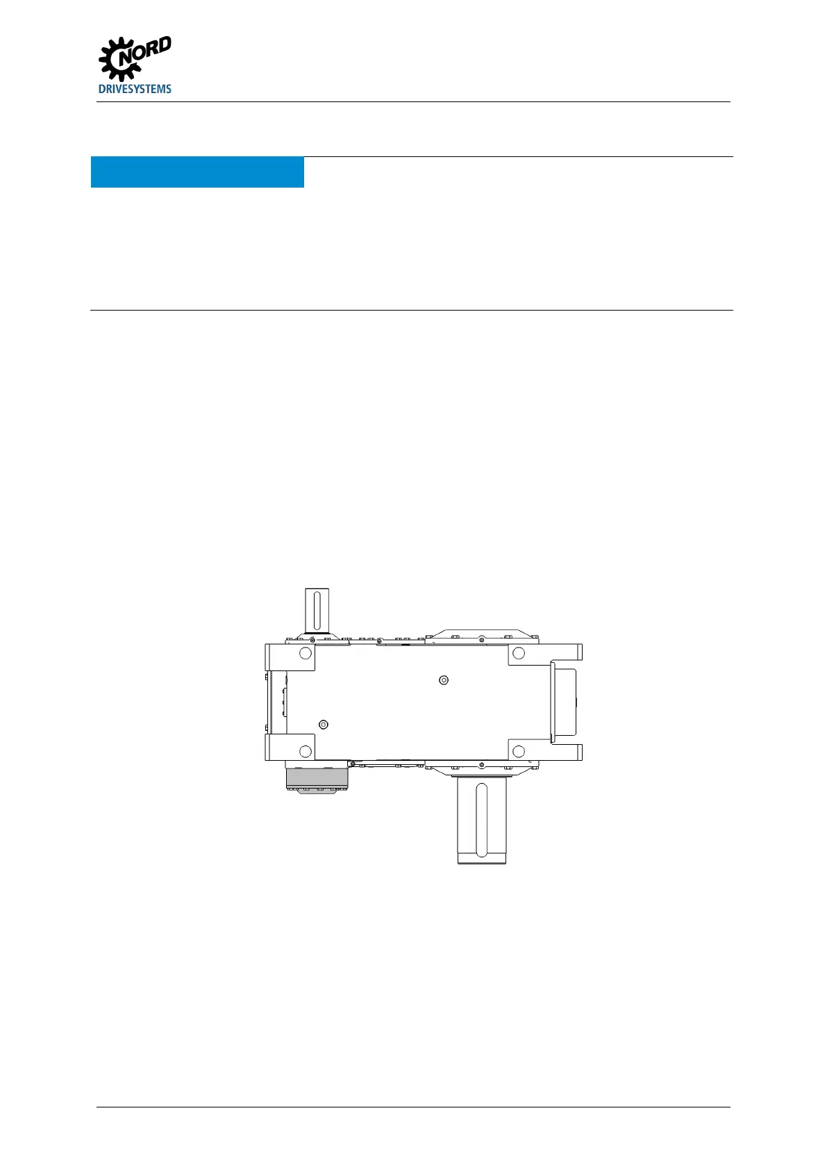
Figure 25: Industrial gear unit with backstop (schematic diagram)
 Loading...