Industrial gear units – Operating and Assembly Instructions
26 B 1050 en-1819
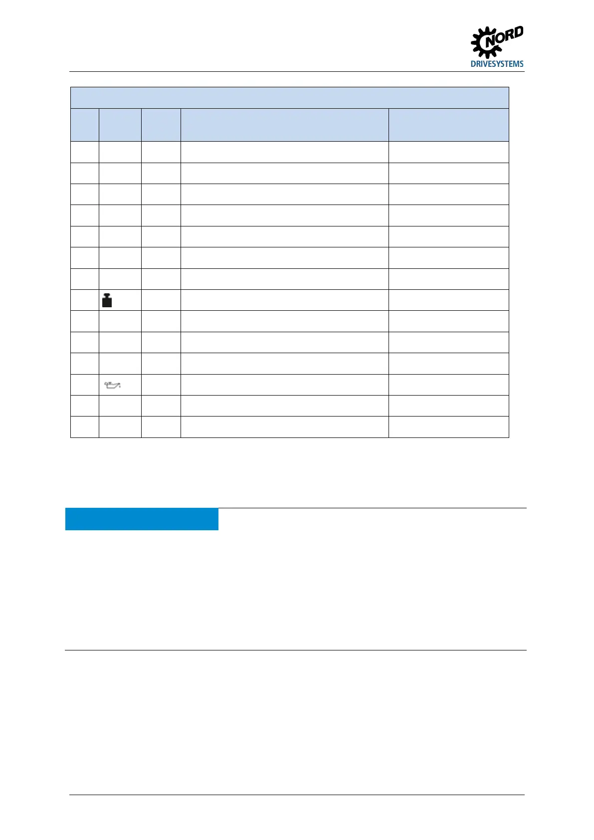
Explanation of the type plate
No.
Abbrevi
ation
Unit Designation See Section
1
- Matrix – Barcode
2
Type SK - NORD gear unit type 2.1
3
- Operating mode
4
- Year of manufacture
5 No. - Serial number
6
M
2
Nm Rated torque of gear unit output shaft
7
P
1
kW Drive power
8
kg Weight according to ordered version
9
i - Overall gear unit ratio
10
- Installation orientation 7.2
11 n
2
rpm Rated speed of gear unit output shaft
12
- Lubricant type, viscosity and quantity 7.3.2
13
- Customer’s part number
14 f
B
- Operating factor
Table 4: Explanation of type plate
Pos: 50 /A nl eitu nge n/G etr iebe /3. Mont ag e, L ager ung , V orber eitung , Aufs tellu ng/Pr üfung der Bauf orm [B10 50] @ 17 \mod_1493037409736_388.docx @ 2342347 @ 2 @ 1
3.6 Checking the version
NOTICE Gear unit damage
The version must be checked and the gear unit may only be commissioned if:
• The gear unit is installed in the correct installation position (7.2 "Installation orientation") according to the
details on the type plate(3.5 "Checking the type plate data").
• The installation position cannot change during operation.
• All of the attachments provided have been used.
• Oil level inspection points, oil drains and venting devices are freely accessible (7.1 "Standard positions of the
oil drain, vent and oil level").
Pos: 51 /Allge mein /All ge meing ül tig e M odul e/---------Sei tenum bruch ko mpakt --------- @ 13\mod_1476369695906_0.docx @ 2265495 @ @ 1
 Loading...