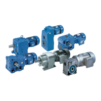
Industrial gear units – Operating and Assembly Instructions
46 B 1050 en-1819
Pos: 85 /A nl eitu nge n/G etr iebe /3. Mont ag e, L ager ung , V orb erei tung , Aufs tell ung /U mlauf sc hmier ung _0 1_( Mont ag e) [ B10 50, B205 0] @ 3 0\mod_1552924845189_388.docx @ 2511262 @ 2 @ 1
3.17 Lubricant circulation (Option: LC, LCX)
Pos: 86 /A nl eitu nge n/G etr iebe /3. Mont ag e, L ager ung , V orb erei tung , Aufstellung/Umlaufschmierung_03_(Montage) [B1050, B2050] @ 30\mod_1552924926543_388.docx @ 2511336 @ @ 1
NOTICE! Gear unit damage
The separate manufacturer’s documentation must be observed for assembly of the motor pump, the external
cooling system and the sensors.
Flanged or motor pumps are used as standard for gear units with lubricant circulation. These are
already installed on the gear unit on delivery and all lines are correctly connected.
The flange pump is driven via the gear unit drive shaft. Motor pumps have a separate drive.
Lubricant circulation systems are normally equipped with pressure switches. The connection and
evaluation of these sensors must be ensured by the operator.
Combination with external cooling units
In the case of combination of lubricant circulation with external cooling units the pressure and intake lines
between the lubricant circulation and the cooling unit must be connected during the installation of the gear unit.
The connection points should be obtained from the specific dimension sheet for the order.
Pos: 87 /A llg em ein/ Allg em eing ülti ge M od ule/ ---------Seite numbruc h kom pakt --------- @ 13\ mod_1476369695906_0.docx @ 2265495 @ @ 1

 Loading...


