Industrial gear units – Operating and Assembly Instructions
44 B 1050 en-1819
Pos: 82 /A nl eitu nge n/G etr iebe /3. Mont ag e, L ager ung , V orb erei tung , Aufs tell ung /Ex ter ne K ühl anlag e_ 01_( Mo ntag e) [ B1050, B2050] @ 3\mod_1369224708230_388.docx @ 70853 @ 2 @ 1
3.16 External cooling system (Option: CS1-X, CS2-X)
Pos: 83 /A nl eitu nge n/G etr iebe /3. Mont ag e, L ager ung , V orb erei tung , Aufs tell ung /Ex ter ne K ühl anlag e_ 03_( Mo ntag e) [ B10 50, B2 050 ] @ 30\mod_1552924402092_388.d ocx @ 25 111 45 @ @ 1
NOTICE!
Gear unit damage
The separate manufacturer’s documentation must be observed for assembly.
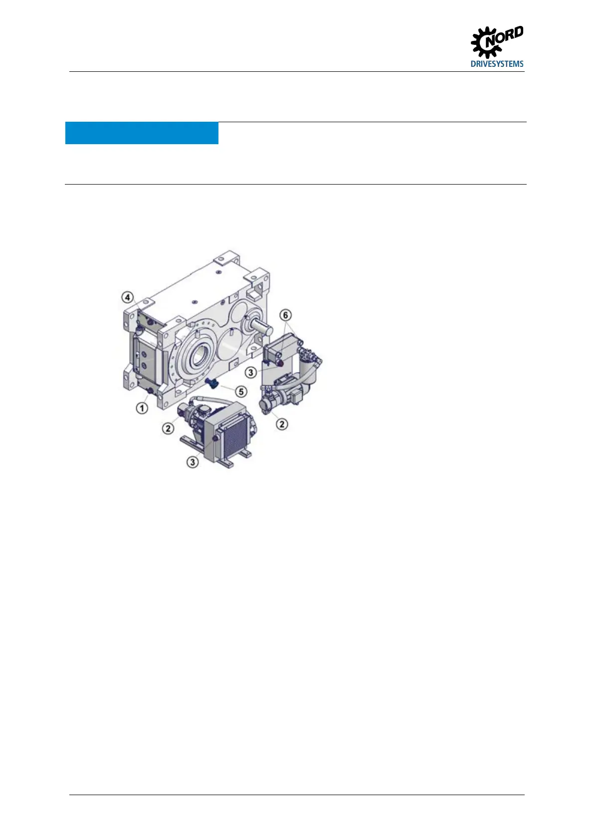
Connect the cooling system as shown in Figure 17. In consultation with NORD, other connection
points may be agreed. These must be obtained from the specific dimension sheet for the order.
Explanation
Gear unit intake connection
2 Pump / cooling system intake
connection
connection
Gear unit pressure connection
PT100 temperature monitoring
(optional/recommended)
Figure 17: Industrial gear unit with CS1-X and CS2-X cooling systems
 Loading...