Industrial gear units – Operating and Assembly Instructions
38 B 1050 en-1819
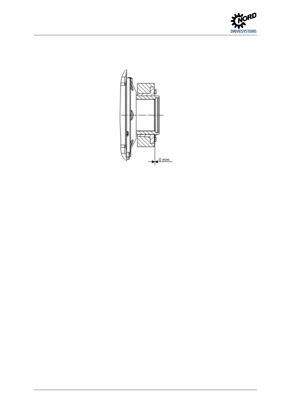
8. After tightening the tensioning bolts the face of the inner ring on the screw side must be flush with
the face of the outer ring. The shrink disc must be checked visually for distortion (Figure 13).
Figure 13: Fitted shrink disc
9. The hollow shaft of the gear unit and the solid shaft of the machine should be marked in order to
detect any slippage under load.
Standard disassembly procedure:
1. Evenly loosen the tensioning bolts of the shrink disc in sequence in the clockwise direction in
several stages. Do not remove the tensioning bolts from their thread.
2. If the external ring does not detach from the inner ring after approx. one turn of all screws, the
external ring can be released with the aid of the push-off thread. For this, the required number of
tensioning bolts are uniformly screwed into the push-off thread until the external ring separates
from the internal ring.
3. The gear unit is removed from the solid shaft of the machine by pushing against the hollow shaft.
If a shrink disk has been in use for a long period or is dirty, it must be dismantled, cleaned and the
conical surfaces coated with Molycote G Rapid Plus or a similar lubricant before it is refitted. The
threads and head surfaces of the screws must be treated with grease without Molykote. Any damaged
or corroded elements must be replaced.
Pos: 68 /Allgemein/Allgemeingültige Mod ul e/---------Seite numbruc h kom pakt --------- @ 13\mod_1476369695906_0.docx @ 2265495 @ @ 1
 Loading...